Bestio Fuel Sender Gauge Wiring Diagram
Fuel Gauge Sending Unit Wiring Diagram Cadician's Blog
This is referred to as a 0-90 O sender. The fuel gauge used must match the sender. What that means is the ohms (O) need to be the same for empty and full on the gauge and sender. That is why you will see kits for GM that have a 0-90 O fuel gauge, because it will work with the stock GM 0-90 O sender.
VDO fuel gauge dip tube help LandyZone Land Rover Forum
Fuel gauge wiring is an essential component of a car's electrical system that provides information about the level of fuel in the tank. It plays a crucial role in ensuring that drivers have accurate and reliable information about their fuel consumption and remaining fuel level.
3 wire fuel sending unit wiring diagram SatyaCampbell
0:00 / 1:12 FUEL SENDING UNIT WIRING DIAGRAM Chef Truck Mechanic 3.21K subscribers Subscribe Subscribed 209 Share 52K views 2 years ago Car starting system wiring diagram EASY.
Wema Fuel Sender Wiring Diagram
"How Do You Wire A Fuel Gauge?Watch more videos for more knowledgeFuel Gauge & Sending Unit Troubleshooting - YouTube https://www.youtube.com/watch/z4c8_NnBW.

Symptoms of a Bad or Failing Fuel Gauge Sender YourMechanic Advice
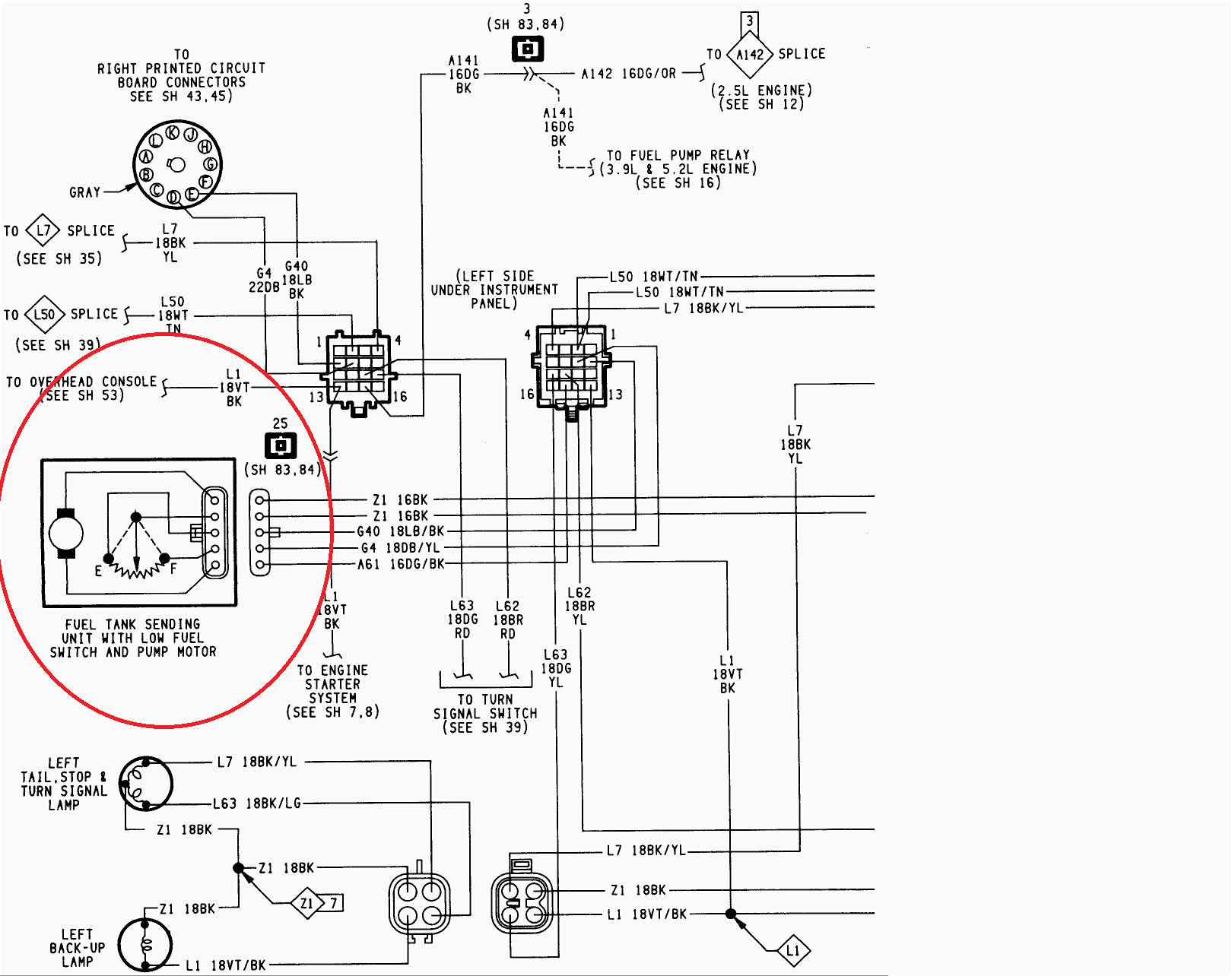
Fuel sender unit wiring and tubes. My wiring diagram shows three wires at my fuel gauge. Power, ground, and pink circuit 30 running to the fuel tank's sender unit. All three are shown running to a rectangle of boxes with circuit numbers in the boxes. one wire runs to directly to metal on the inside of the cab (ground I assume);
Fuel Gauge BAYLINER OWNERS CLUB
95 YJ fuel gauge to sender wiring, and testing. My gauge always reads full so i started reading a bunch of threads here and running tests but I'm stuck now. Disconnected the fuel sender plug, ohms at the sender read 37, sitting just under half a tank which seems correct. Center pin to chassis ground from gauge harness side drops to E which is.
Wema Fuel Sender Wiring Diagram Knit Inc
The fuel gauge works off resistance. For instance, mine is a 0-90 ohm sender. 0=empty, 90=full. If a wire is disconnected it's pretty much reading infinite resistance so it'll read over full. Check your connections and your grounds. Doug II. Currently shopping for 20" billets. Raceline, BAD, Turbines, Billet Specialties, Etc.

Wema Fuel Sender Wiring Diagram Easy Wiring
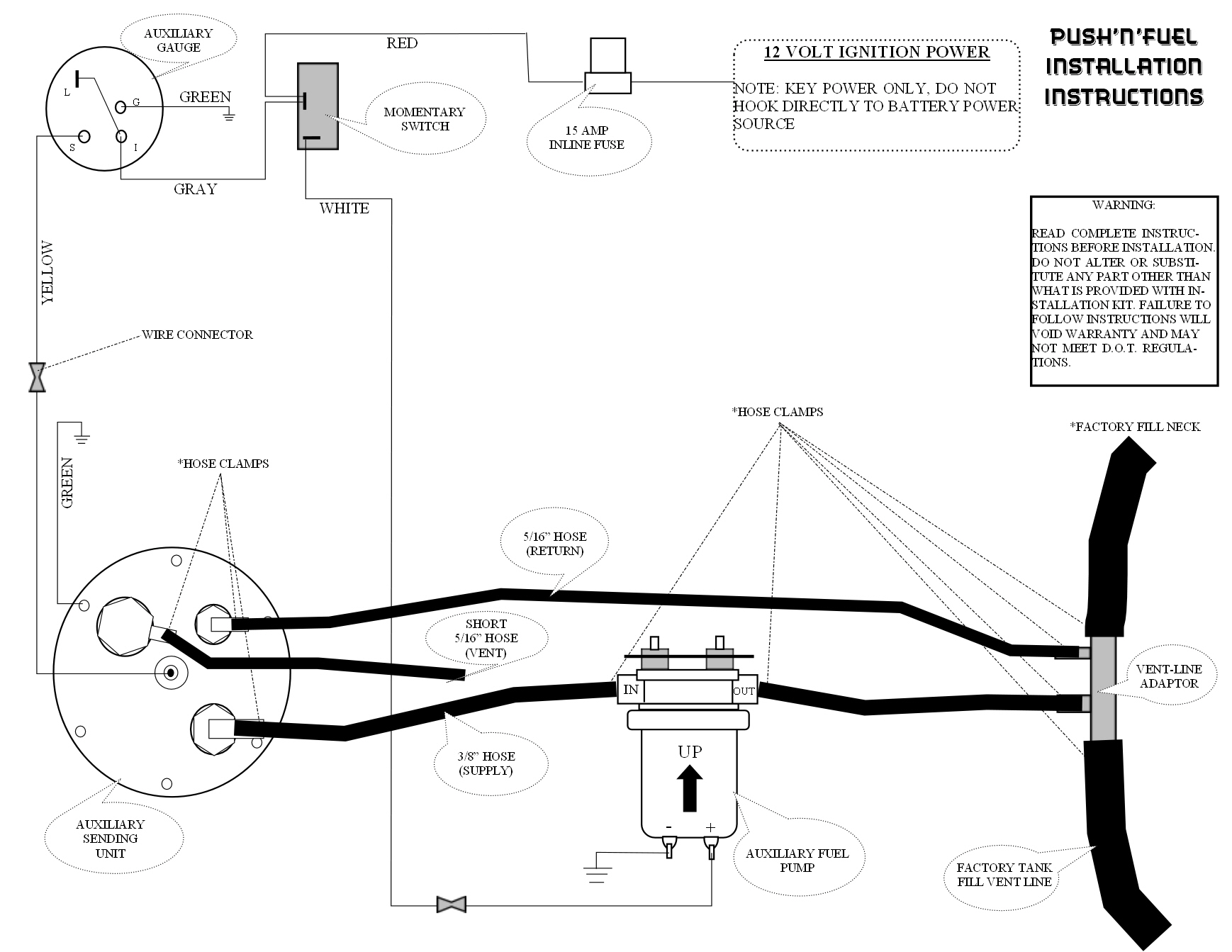
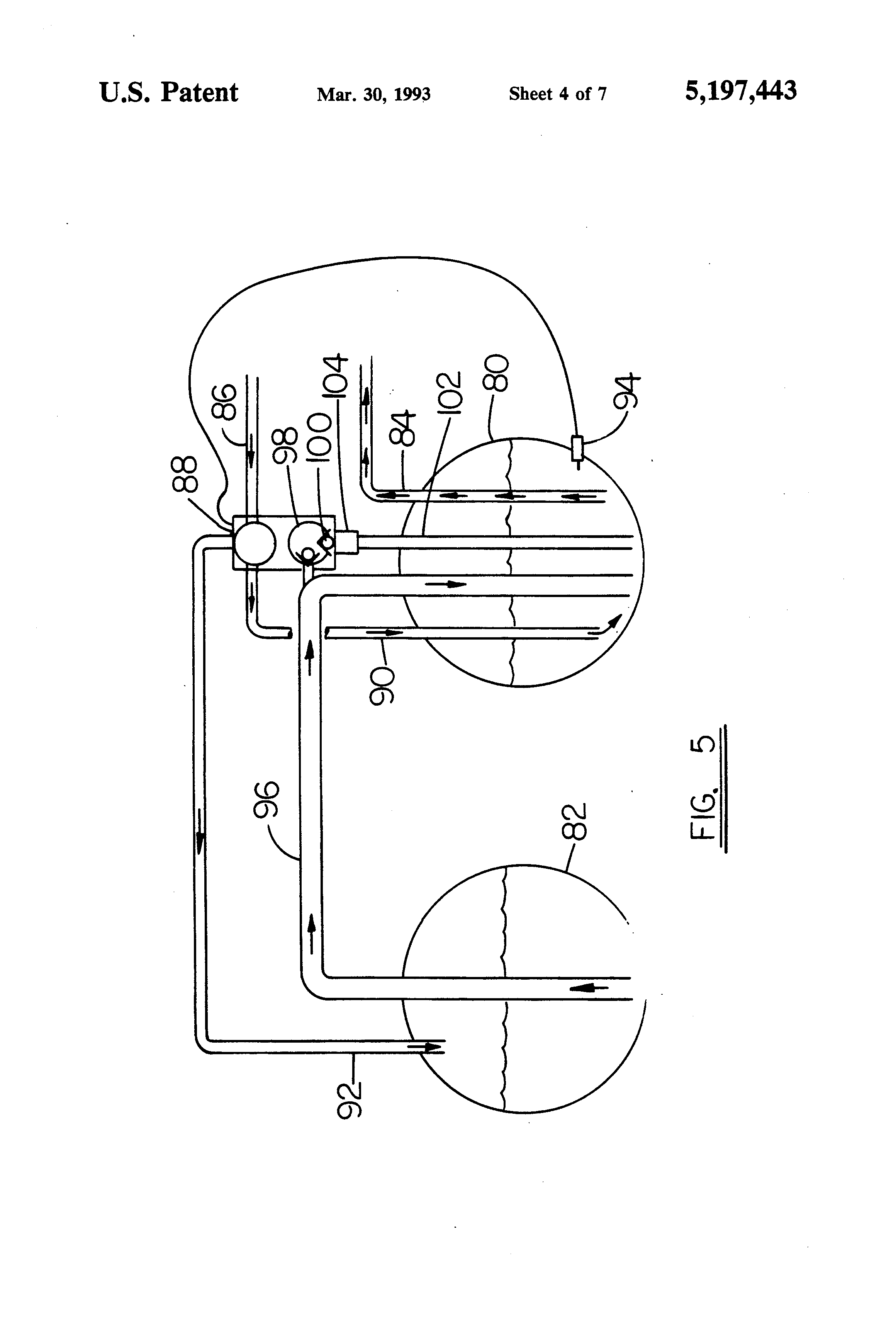
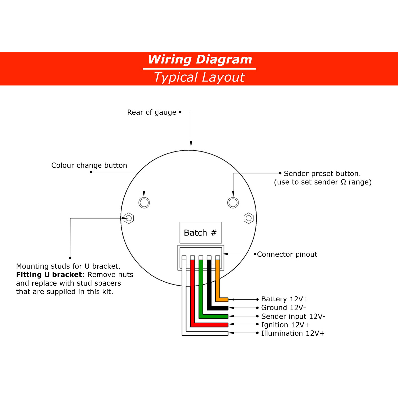
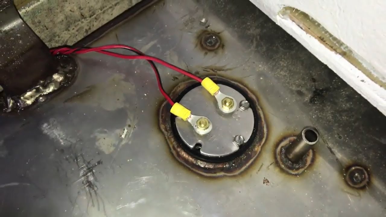
Proper Wiring Installation (See Figure 5): Connect sender wire from fuel gauge to the threaded screw terminal on sender. Connect ground wire to 1/4" fasson terminal on sender. GASOLINE IS EXTREMELY FLAMMABLE! KEEP TANK AREA FREE FROM SPARKS AND FLAMES. EMPTY TANK OF FUEL AND FUMES BEFORE CONTINUING WITH INSTALLATION.
SAAS Fuel Level Gauge Black Muscle Series 52mm Autobox
I. Turn on the dash light switch to see if all gauges light up. If not, check your wiring, the ground, and all bulbs. Reconnect or replace as necessary. II. Turn on the ignition key. Gauges should read: Pressure: Needle to 0 Fuel: Needle to amount of fuel in the tank Temperature: Needle to the temperature of the engine water.
International Bus Fuel Gauge Wiring Diagram New Wiring Resources 2019
In most cases, the sender and the fuel gauge need to be matched to the resistance in the sender's rheostat, so to be completely sure you are getting accurate readings, replace both the sender and the gauge. Several companies provide pre-packaged "ready-to-go" installation kits. How Tank Sensors Work
Troubleshooting Boat Gauges Soundings Online
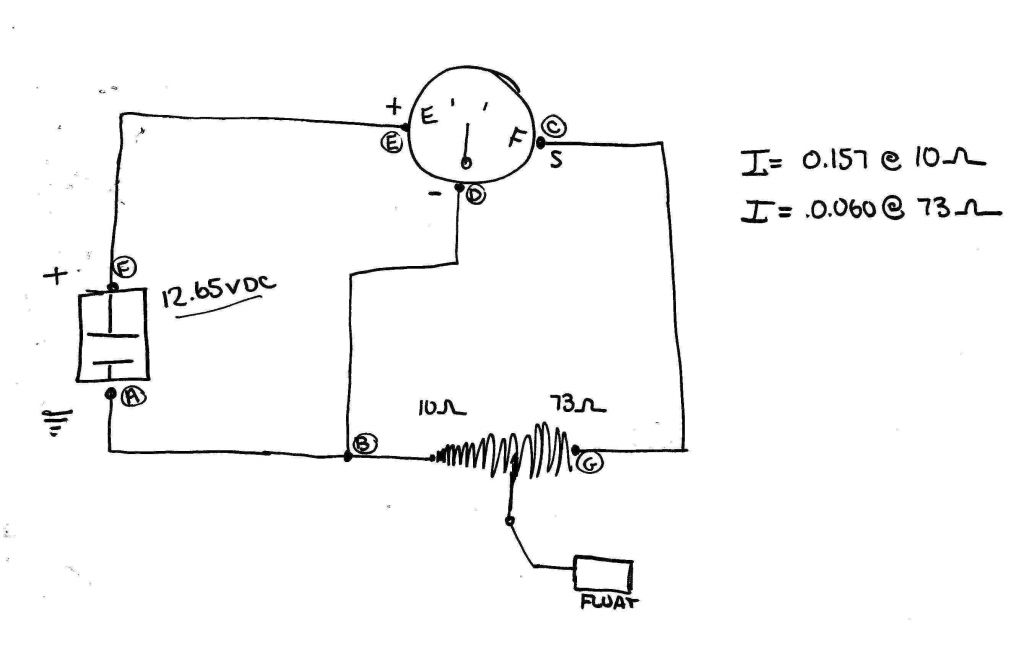
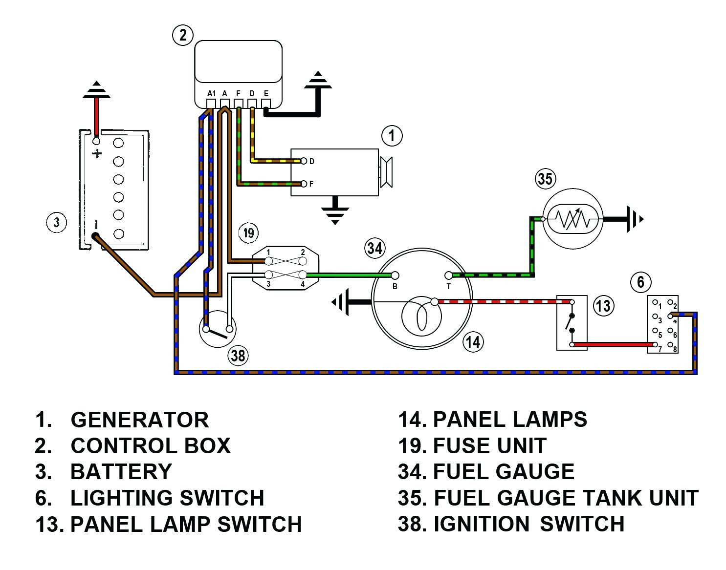
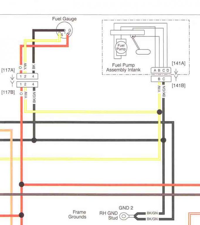
Fuel Tank Indicating system is active when Ignition Power is ON and is on the Fuse1 circuit, as can be seen in this detailed wiring diagram extract. Fuel Gauge circuit, 12V showing circuit details. Fuel Sender and Gauge Electrical Calculations: Full Tank: I tot = 12 / R tot = 12 / (9.68 + 142) 151.6Ohms = 79.2mA
Hawke Dump Trailer Wiring Diagram Wiring Diagram
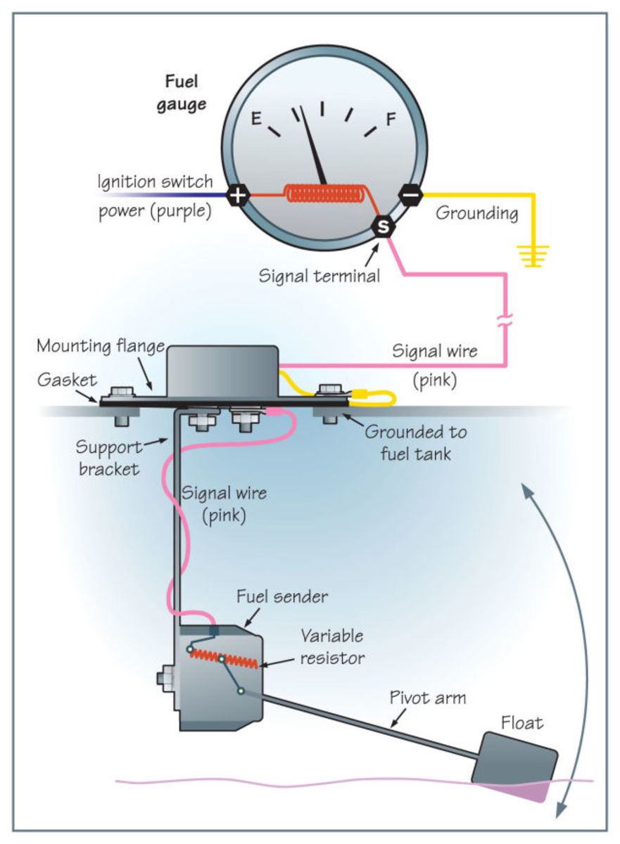
The fuel gauge measures voltage using the fuel level sender that comes with a variable resistor. After that, the level of the fuel tank will be shown on the dashboard indicator. The fuel level sender has three parts; a metal rod, a variable resistor, and a float. The above process will run smoothly if all the wire connections are perfect.
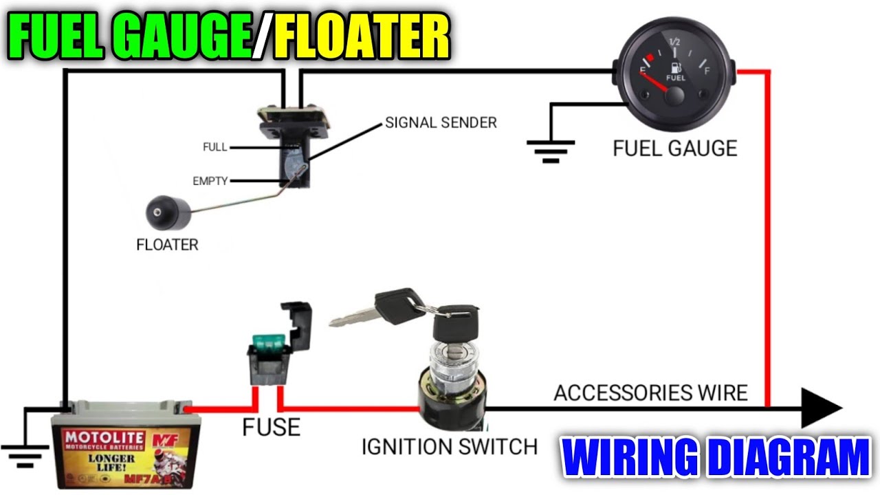
FUEL GAUGE/FLOATER WIRING DIAGRAM FUNCTIONS AND CONNECTIONS YouTube
Step 1: Locate the Fuel Sending Unit Step 2: Test the Fuel Gauge Step 3: Repairing Faulty Wiring Step 4: Remove the Faulty Fuel Sending Unit Step 5: Test the Old Fuel Sending Unit Step 6: Install the New Fuel Sending Unit Safety Precautions Wrap Up What Is a Fuel Sending Unit
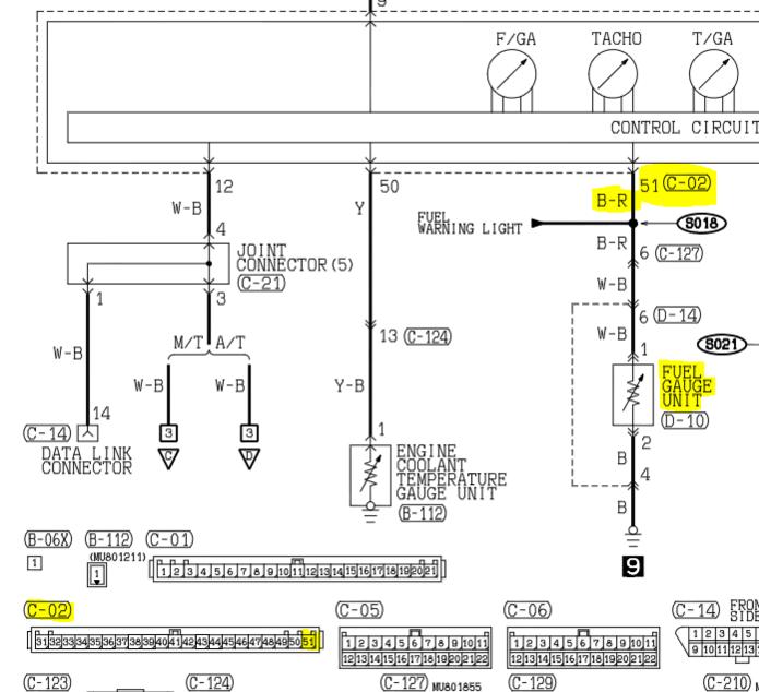
Fuel Sender Wire color EvolutionM Mitsubishi Lancer and Lancer
An old-school approach to quickly diagnose your fuel sending unit and the gauge. Most times, the wiring is bad. Use this video as a reference.Heres a link to.
How to Wire a Fuel Gauge in a Boat? Boating Buddy
.1. Remove nut "a", washer "b", and ring terminal "c" from the underside of the mounting flange. .2. Loosen the two screws marked "d", Adjust the plastic housing up or down until the proper dimension from Tables 1 is obtained, and then re-tighten the screws securely. DO NOT over tighten.
Fuel Sender Wiring Diagram Wiring Diagram
I had to use the sending unit supplied with my VDO fuel gauge because it registers empty at 10 ohms and full at 180 ohms, the same as new VDO gauge senders. The standard aftermarket senders now measure the fuel capacity at 33 ohms empty and 240 ohms at full. Bolt pattern was rotated slightly to match the six-hole pattern on my stock '32 tank.
