6 Terminal Ignition Switch Wiring Diagram Briggs And Stratton 6
Step-by-Step Instructions. Once you've gathered the necessary components, you can begin the wiring process: 1.Start by connecting the battery cable to the negative terminal of the battery. 2.Connect the hot wire to the positive terminal of the battery. 3.Connect the red wire to the ignition switch. 4.Connect the black wire to the ignition.

6 prong ignition switch wiring diagram Wiring Diagram
Here are some tips to help you troubleshoot a 7 pin ignition switch: Check the wiring connections: Start by inspecting the wiring connections. Ensure that all the wires are securely connected to their respective terminals. Look for any loose or damaged connections that may be causing the problem.
5 Pin Ignition Switch Wiring Diagram
ENGINERUN 725-1717 Ignition Key Switch (7 Prong) Compatible with AYP Briggs MTD Murray Husqvarna Replaces 334013B 532140301 9251717 92556 5412H Mowers. Add to Cart . Add to Cart. Genuine Briggs & Stratton replacement ignition switch that fits most electric starter engine with a 7-terminal switch. Product information . Brand : Briggs.

Mtd Troy Bilt 21hp Briggs Wiring Diagram 6pin
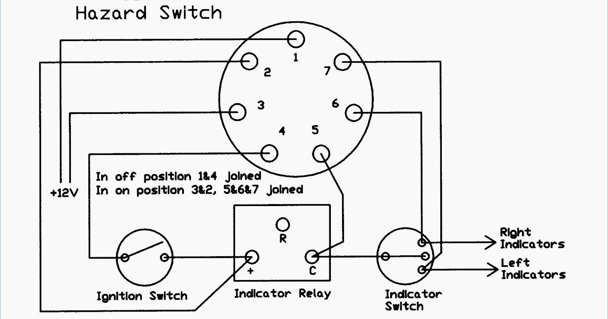
A 7 prong ignition switch wiring diagram will usually have seven different connections, labeled as 1-7. These connections, when wired together, create the power supply to the vehicle's engine. Additionally, there may be a few additional connections, such as ground terminals and a power terminal.

Műhely Ébredés Maréknyi 6 pin switch wiring diagram Részleges füst
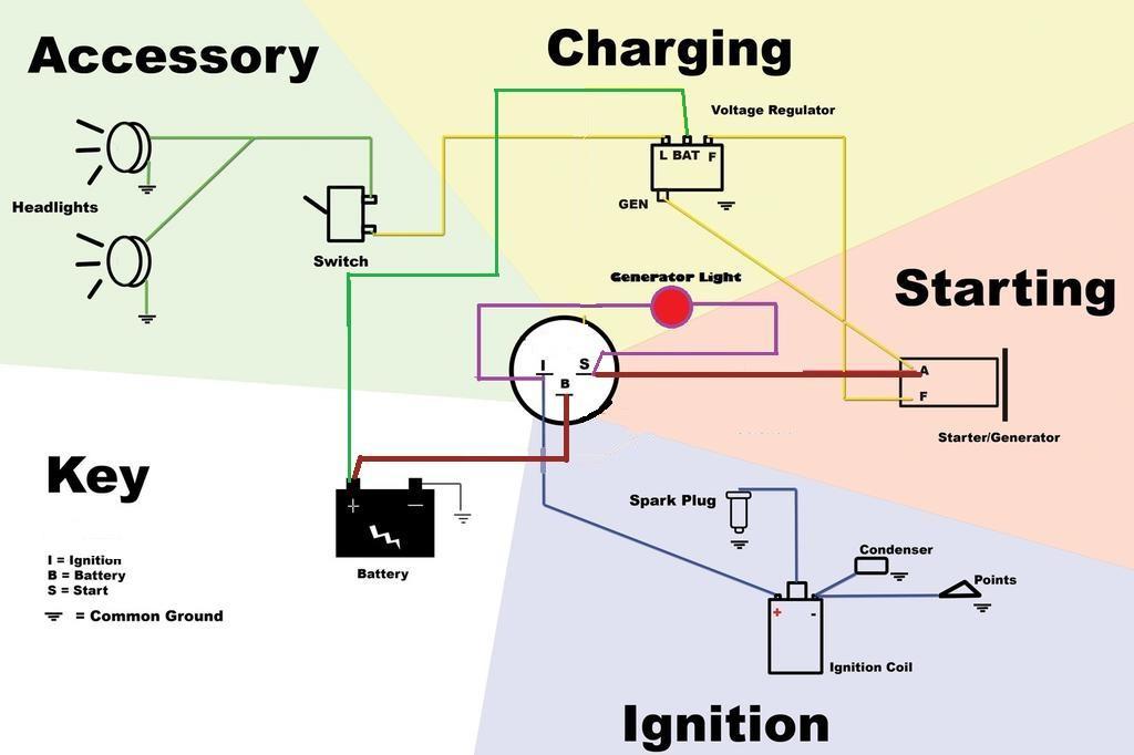
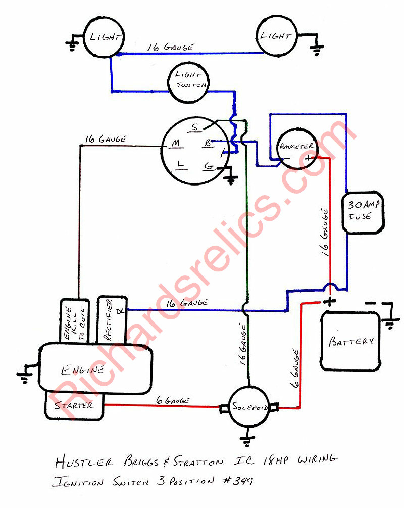
Step 1: Obtain a circuit diagram. Step 2: Locate all components that need wiring. Step 3: Connect the switch to ground. Step 4: Connect the switch to the Solenoid. Step 5: Wire the magneto to the switch. Step 6: Provide voltage by connecting the battery. Step 7: Connect the accessories/ lights.

6 Prong Briggs Ignition Switch Wiring Diagram Database Wiring
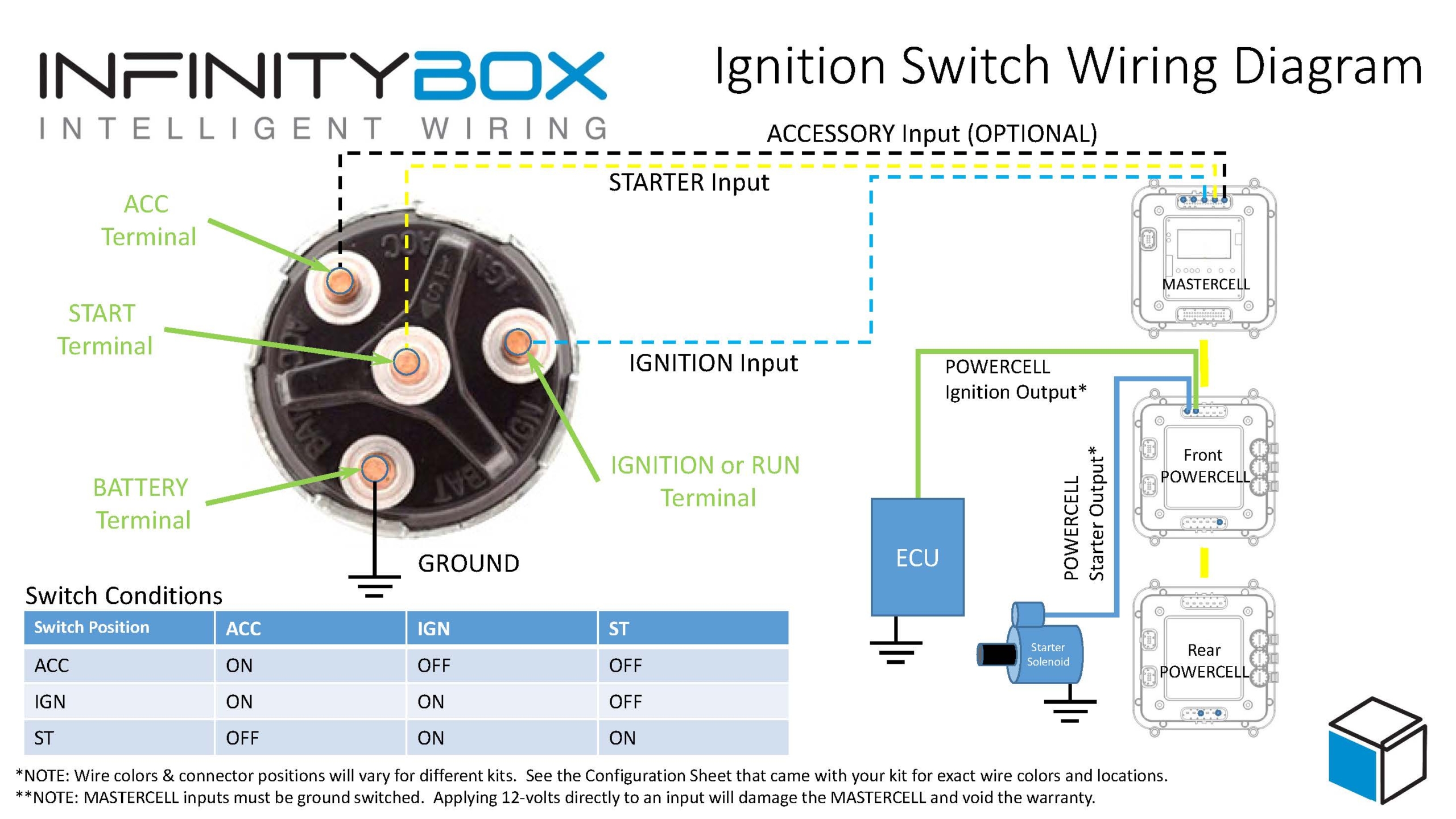
A standard ignition switch, like the MTD 7 Pin, is made up of five or six pins. The diagram allows you to connect wires from different parts of the vehicle - such as the starter motor, an alternator, or the distributor - with the appropriate pin on the switch itself. The wiring diagram shows which wire goes to which pin on the actual switch.
Wiring Diagram For Lucas Ignition Switch Wiring Diagram and Schematic
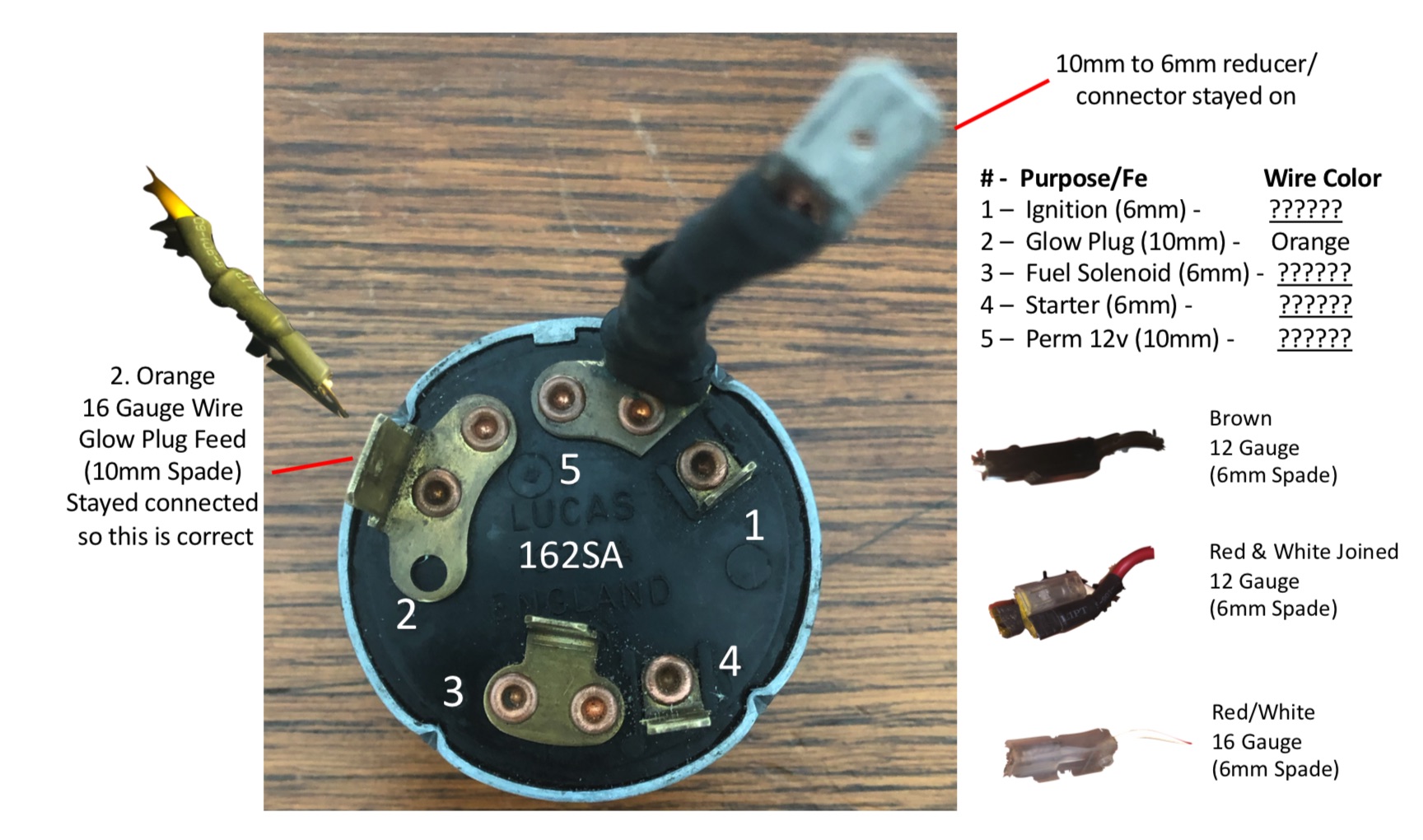
Let's use your continuity tester. Ask Your Own Small Engine Question. ok. Technician: Donald. Look at the bottom of your ignition switch. Each one of your seven prongs will have an identifying letter either stamped into it, or stamped next to it. Look for a ( B) and a ( S ). Ask Your Own Small Engine Question. ok.
7 Prong Ignition Switch Wiring Diagram Wiring Harness Diagram
Prong Ignition Switch Diagram: A Comprehensive Guide. Understanding the wiring and connections of a 7-prong ignition switch is crucial for anyone working with automotive electrical systems. The ignition switch is an essential component that controls the flow of electricity from the battery to the starter motor, allowing the engine to start and run.
7 Prong Ignition Switch Wiring Diagram Wiring Harness Diagram
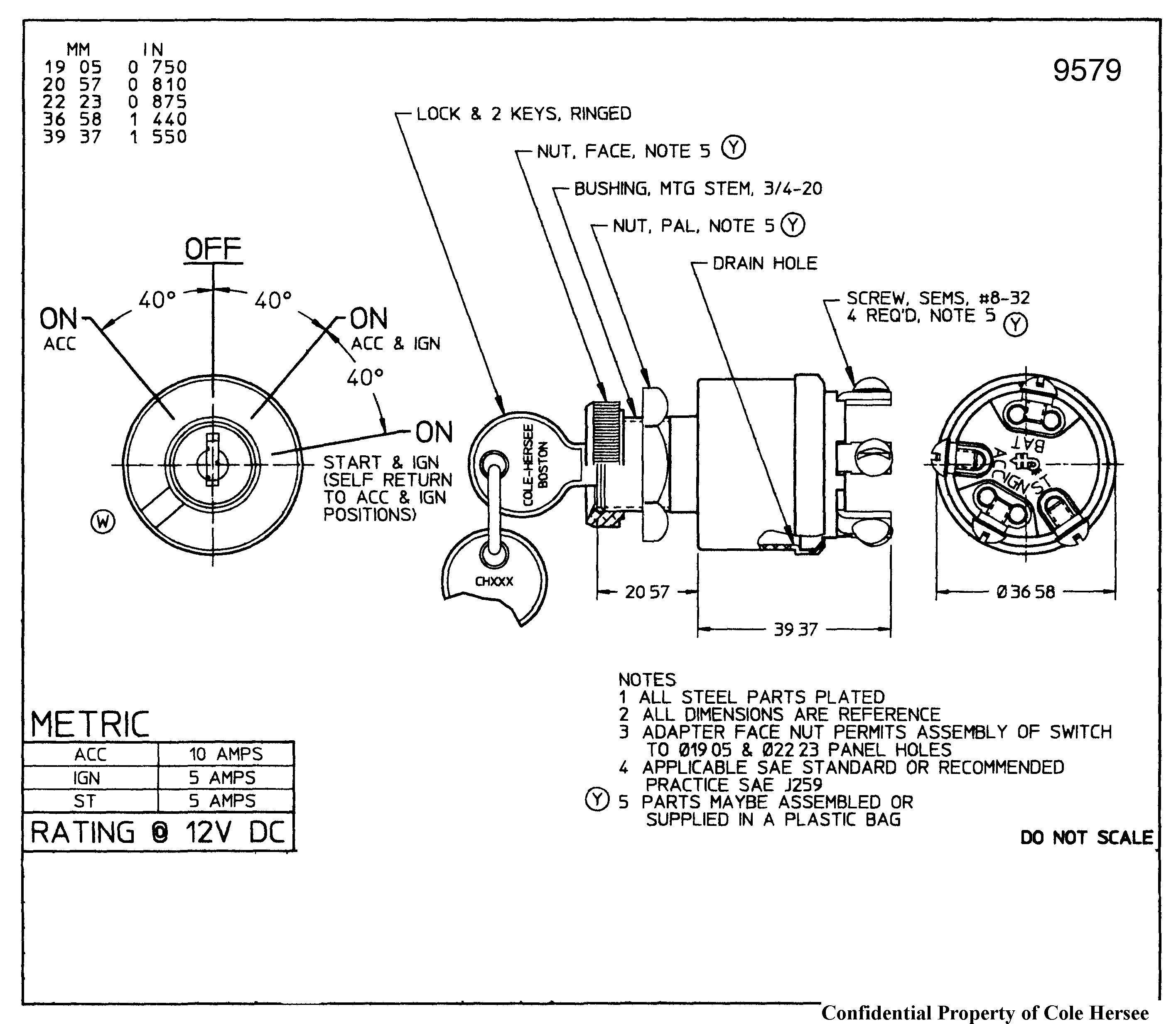
Connect Wires. Start with the positive lead from the car battery going to the ignition switch. It's often a red wire that's thick and constantly energized. Fit the terminal end from the power lead wire and secure it. Connect this lead to the BATT terminal of the switch. Connect the accessory wire to the ACC terminal next.
The Wiring Diagram Of An Ignition Switch Explained Moo Wiring
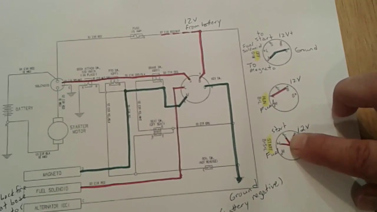
Two pictures are attached - the old wiring into the old ignition and the new ignition. Old ignition had three connections: -IGN. -ST. -BAT. There were four wires going into the old ignition - here is what I believe they connect to: -green - volt meter.
5 Prong Ignition Switch Wiring Diagram
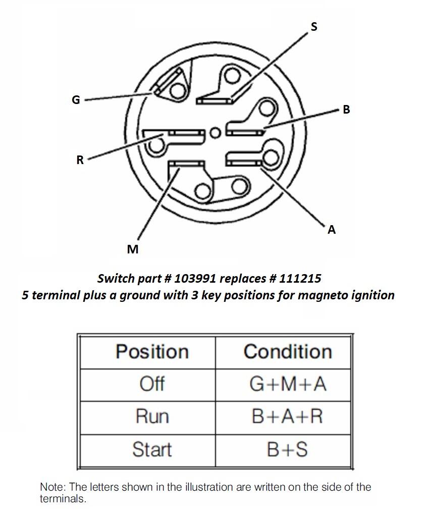
Location: Western NC. #1. Posted June 12, 2018 (edited) I have a few basic electrical system diagrams that are helpful in understanding how the wiring system works. They are not specific to any particular tractor and do not include safety switches. All use the 5 post ignition switches 103-991 for Magneto and 103-990 for Battery Ignition.
7 Prong Ignition Switch Wiring Diagram Wiring Harness Diagram
Having a riding lawn mower with a 7 prong ignition switch can be a great way to make mowing your lawn easier. However, if the switch isn't working properly, it can be difficult to know what to do. Testing the riding lawn mower 7 prong ignition switch is an important step to ensure that it is working correctly and that your mower is in good running order.

7 Prong Lawn Mower Ignition Switch Wiring Diagram
Jul 17, 2019 / Ignition Switch wiring codes. #2. The answer is they don't because those two switches are not interchangeable. The are wired different and will cause other issues by sending 12 volts to things that are not designed to have power like the ignition modules. B.

craftsman 7 terminal ignition switch wiring diagram
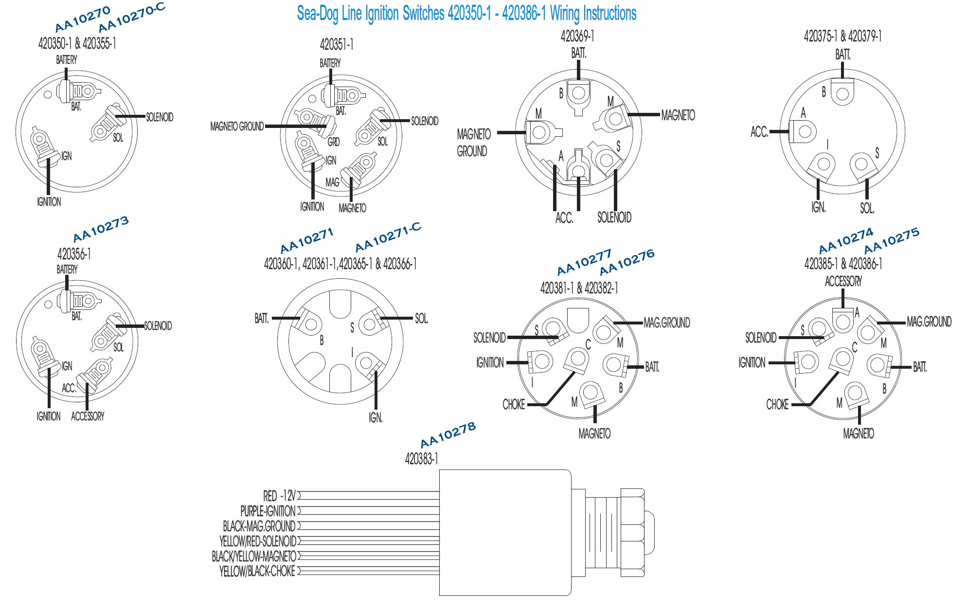
Understanding the wiring diagram for a 7 prong ignition switch is essential for troubleshooting, repairing, or replacing the switch. A 7 prong ignition switch typically consists of seven terminals or prongs labeled with different letters, such as B, M, S, I, R, A, and C. Each terminal has a specific function and connects to different parts of.