Principal ray pattern in InI together with the firstorder sampling... Download Scientific Diagram
Draw ray diagram to show the principal focus of a Tutorix
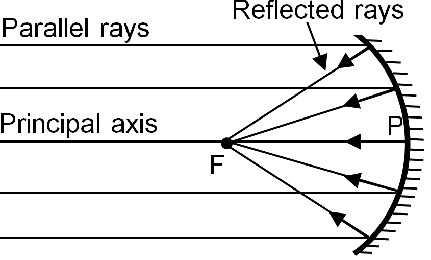
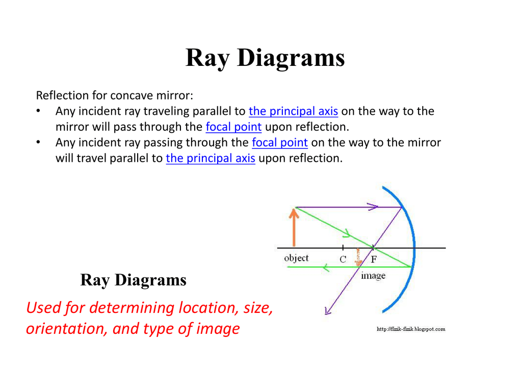
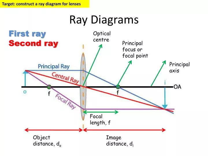
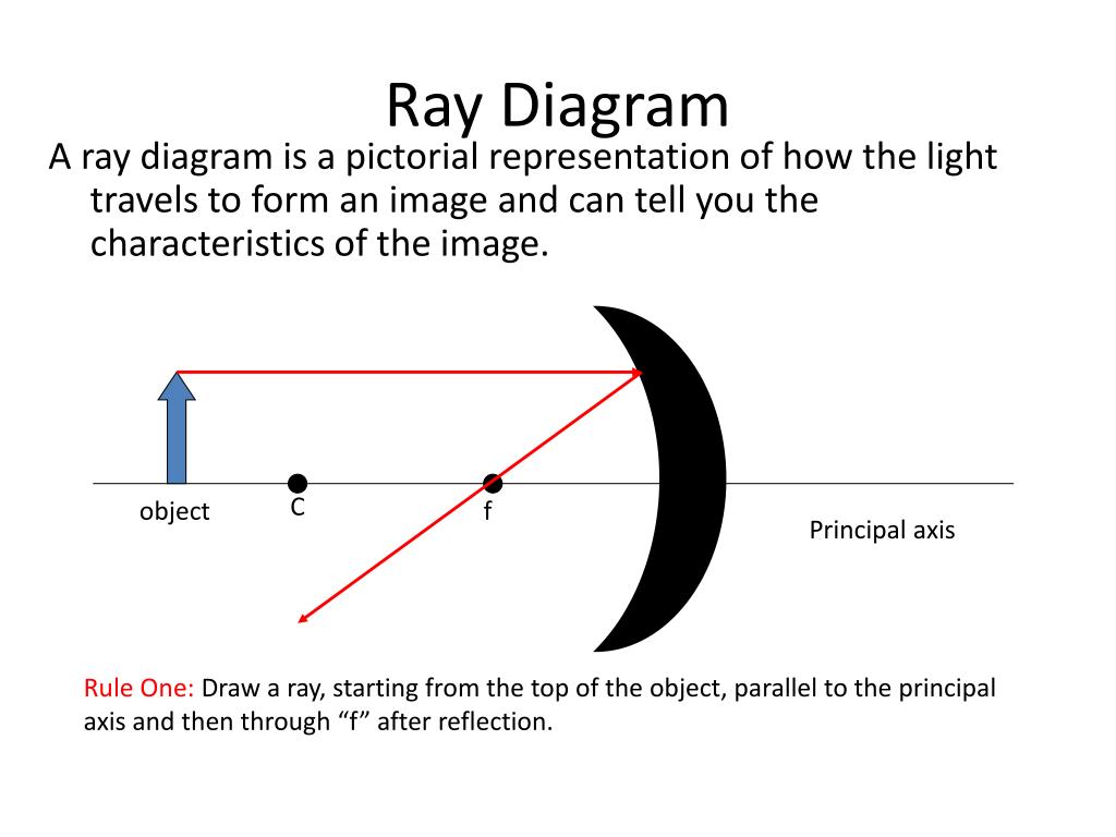
Ray Diagrams. All lenses and mirrors can use ray diagrams to find images. There are three principal rays. The first principal ray occurs when the light comes in parallel to the principle axis, it goes out through the focus. The second principal ray occurs when light comes in through the focus, then it comes out parallel to the principle axis.
Practical ways ways to find the principal focal length len
Describe and predict image formation and magnification as a consequence of refraction through convex and concave lenses, use ray diagrams to confirm image formation, and discuss how these properties of lenses determine their applications Explain how the human eye works in terms of geometric optics
How To Draw Ray Diagrams of all time Don t miss out howtodrawimages1
Diagram of rays at a surface, where is the angle of incidence, is the angle of reflection, and is the angle of refraction. An incident ray is a ray of light that strikes a surface. The angle between this ray and the perpendicular or normal to the surface is the angle of incidence.

Diverging lens principal rays YouTube
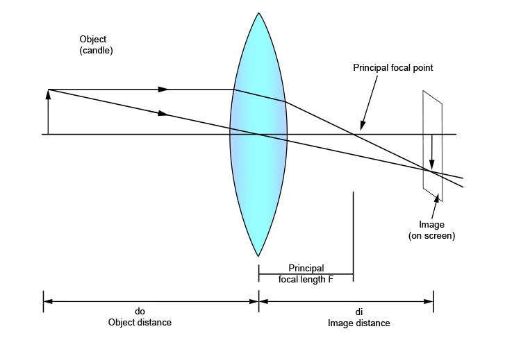
Once through the lens, the ray should pass through the principal focus. Draw a ray which passes from the object through the centre of the lens. Some ray diagrams may also show a third ray.
Ray Diagrams
This physics video tutorial on optics provides a basic introduction into ray diagrams. It explains how to draw ray diagrams for converging lens, diverging lens, concave mirrors, and convex.
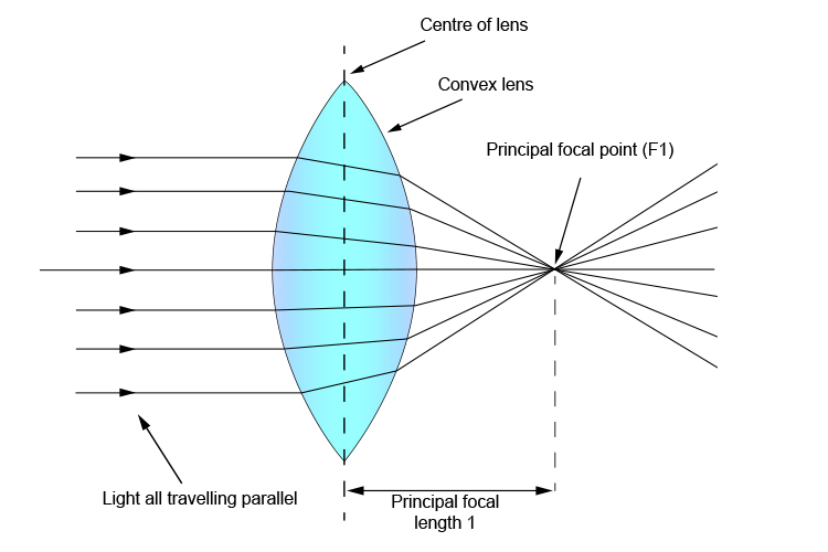
Principal focal length
Using Ray Tracing Diagrams; A lens is a piece of transparent material whose surfaces have been shaped so that, when the lens is in another transparent material (call it medium 0), light traveling in medium 0, upon passing through the lens, is redirected to create an image of the light source.. Principal Ray III, for a converging lens (with.
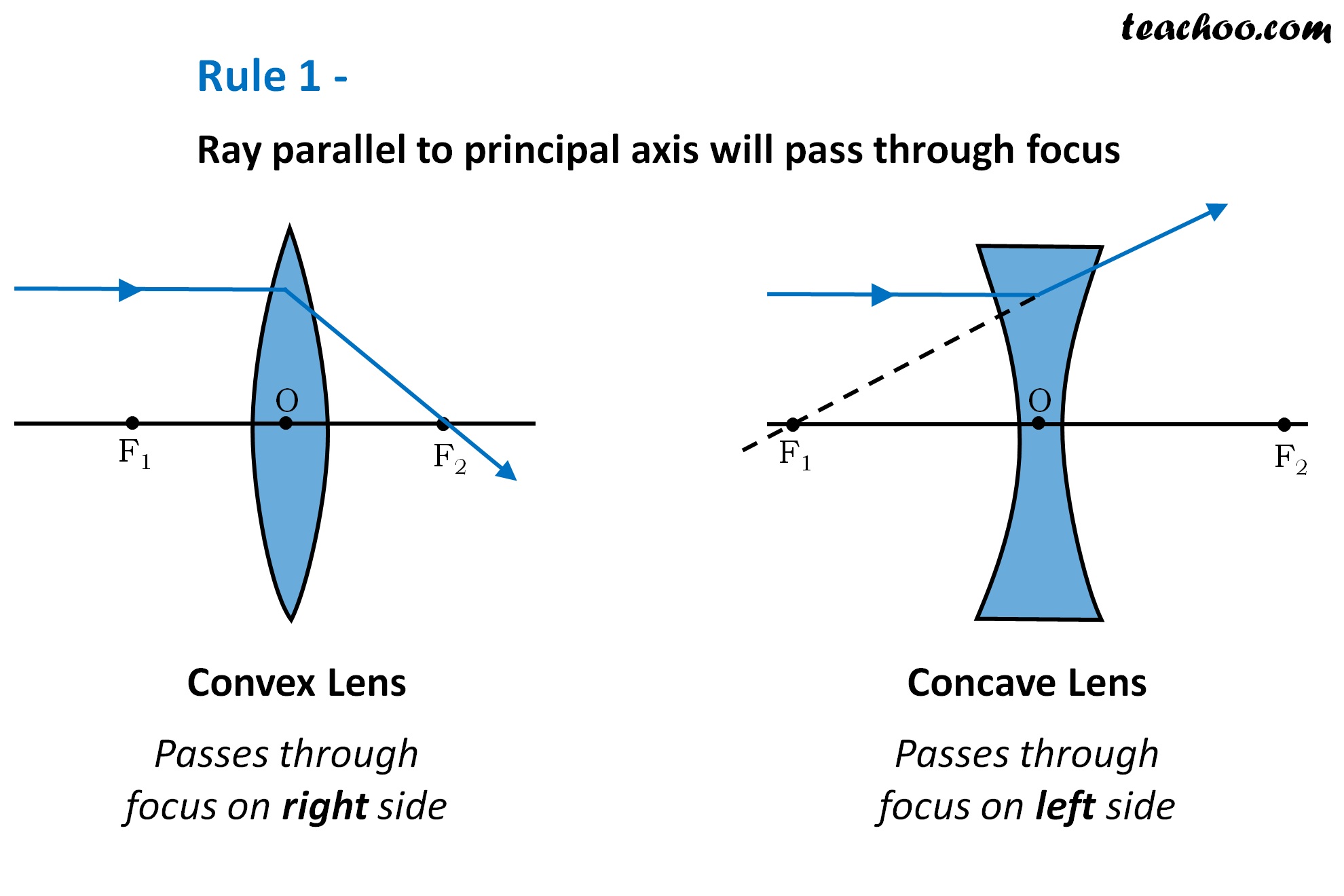
Rules for drawing Ray Diagram in Convex and Concave Lens Teachoo
Use ray diagrams and the mirror equation to calculate the properties of an image in a spherical mirror.. Principal ray 2 travels first on the line going through the focal point and then is reflected back along a line parallel to the optical axis. Principal ray 3 travels toward the center of curvature of the mirror, so it strikes the mirror.

Principal ray pattern in InI together with the firstorder sampling... Download Scientific Diagram
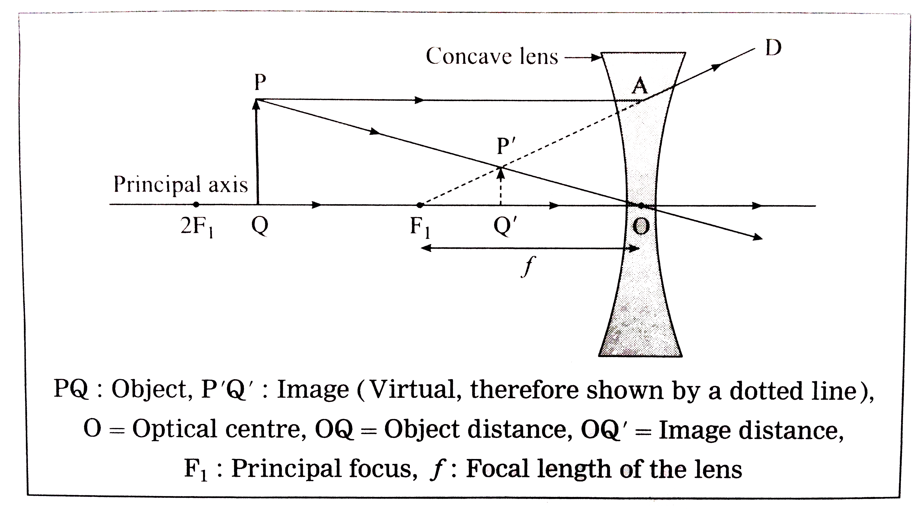
Previously in Lesson 5, ray diagrams were constructed in order to determine the location, size, orientation, and type of image formed by double concave lenses (i.e., diverging lenses). The ray diagram constructed earlier for a diverging lens revealed that the image of the object was virtual, upright, reduced in size and located on the same side of the lens as the object.

Convex Mirror Ray diagram, Images Formed with Steps Teachoo
1. Pick a point on the top of the object and draw two incident rays traveling towards the mirror. Using a straight edge, accurately draw one ray so that it passes exactly through the focal point on the way to the mirror. Draw the second ray such that it travels exactly parallel to the principal axis.
PPT Ray Diagrams PowerPoint Presentation, free download ID4089587
A ray diagram is a tool used to determine the location, size, orientation, and type of image formed by a lens. Ray diagrams for double convex lenses were drawn in a previous part of Lesson 5. In this lesson, we will see a similar method for constructing ray diagrams for double concave lenses. Step-by-Step Method for Drawing Ray Diagrams
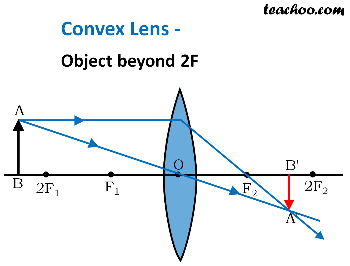
Convex Lens Ray diagram, Image Formation, Table Teachoo
The principal ray is defined as the ray emanating from an off-axis object point that passes through the center of the stop. In the absence of pupil aberrations, the principal ray also passes through the center of the entrance and exit pupils.

[DIAGRAM] Practice Drawing Ray Diagrams
1. Pick a point on the top of the object and draw three incident rays traveling towards the lens. Using a straight edge, accurately draw one ray so that it passes exactly through the focal point on the way to the lens. Draw the second ray such that it travels exactly parallel to the principal axis.

Rules for drawing Ray Diagram in Concave and Convex Mirror Teachoo
Convex mirror has two ray diagrams because its principal focus and the centre of curvature lies behind its reflecting surface. Therefore, not more than two positions of the object can be obtained in relation to these points unlike concave mirrors where more than two ray diagrams are constructed to find out the position of the image for different relative positions of the object.

Rules for drawing Ray Diagram in Concave and Convex Mirror Teachoo
Use ray diagrams and the mirror equation to calculate the properties of an image in a spherical mirror. The image in a plane mirror has the same size as the object, is upright, and is the same distance behind the mirror as the object is in front of the mirror.. (i.e., a virtual focus). Principal ray 2 travels first on the line going through.
PPT Chapter 26 Geometrical Optics PowerPoint Presentation, free download ID438780
A ray diagram is a tool that is used to determine the location, size, orientation, and type of image formed by a mirror. Ray diagrams for concave mirrors were drawn in Lesson 3. In this lesson, we will see a similar method for constructing ray diagrams for convex mirrors. Step-by-Step Procedure for Drawing Ray Diagrams
Principal Ray Diagram Diverging Lens
A completed ray diagram is shown in; The angle in which a light ray hits the mirror is the same angle in which it will be reflected back. If, for example, a light ray leaves the top of an object travelling parallel to the principal axis, it will hit the mirror at a 0 degree angle, and be reflected back at 0 degrees.
