4 Pin Wiring Diagram 4 Pin M12 Pinout Socket Pinout Images For Pinout 7

M12 Wiring Diagram For Kohler Command
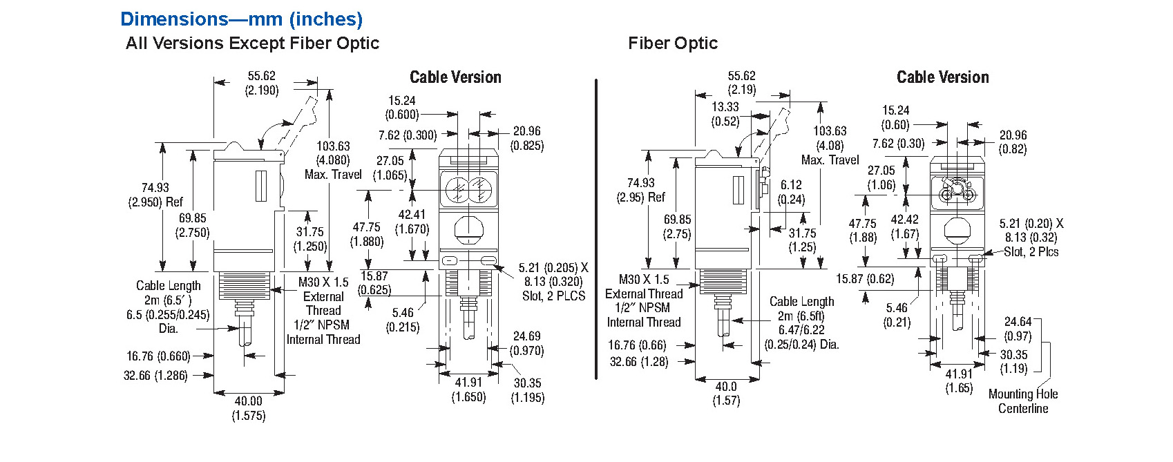
MECHANICAL Dimensions: 60.3 W x 64.31 L x 51.54mm H (2.38" W x 2.53" L x 2.03" H) Materials: PA12, silicone rubber, nickel-plated brass, stainless steel GENERAL Agency Approvals: CE, EMC 2014/30/EU, LVD 2014/35/EU class II product, (low voltage 8 to 28 VDC) 6 M12 8-Pin Connector Wiring Diagram

China Wiring Colour Code Wiring Digital and Schematic
M12 Ethernet wiring diagrams are an invaluable tool when it comes to wiring Ethernet cables and connectors. They provide a concise, visual representation of how the wiring should be connected, as well as a comprehensive list of components that are required.
Female M12 12 Pin Wiring Diagram
Provides support for NI GPIB controllers and NI embedded controllers with GPIB ports. You can request repair, RMA, schedule calibration, or get technical support. A valid service agreement may be required. Open a service request. This document provides the wiring diagram and pinout for the M12 cable as it connects to the NI 9921 or NI 9922.

M12 4 Pin Wiring Diagram M14 Front Panel Mount 8 Pin Wire Connector
Learn how to install an M12 electrical connector to the end of an M12 cable with flying leads.0:00 Start1:04 Connectors Overview2:24 Manual 332305 Wiring Dia.

4 Pin Wiring Diagram 4 Pin M12 Pinout Socket Pinout Images For Pinout 7
The M12 power cable assemblies are available in both male and female connectors and suitable for every purpose with its conductor size from 1.5 mm2 up to 2.5 mm2 allowing for a more compact build of a high-power solutions for automation devices.
4 Pin Wiring Diagram 4 Pin M12 Pinout Collection
The M12 connector typically has 5 pins, each with a specific function in the wiring diagram. Understanding the pin configuration and wiring diagrams for the M12 connector is crucial for proper installation and troubleshooting. The wiring diagram for the M12 connector 5 pin can vary depending on the specific application and manufacturer.
Peplink Transportation Solutions M12 ADVANTESCO
TE Connectivity's M8/M12 Connector System provides one complete solution to safely and reliably ensure efficient communication in industrial environments and decrease downtime. Connector System One complete solution for your requirements

M12 Connector Wiring Diagram
M12 Basic line Cable type XS2F-M12 Water- and Environment-resistive FA Connectors Save Wiring and Maintenance Effort † Compact FA connectors meet IP67 requirements and ensure a 94V-0 fire retardant rating. † A wide array of connectors makes a wiring system more modular, simplifies maintenance, and reduces downtime. † IEC61076-2-101.
Leuze Ht46ci/4pm12 Wiring Diagram
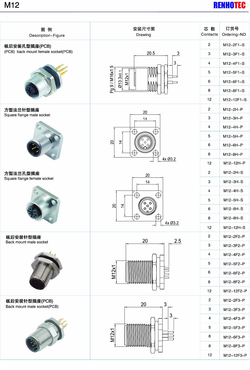
You may identify these coding types of m12 series by below contact layout diagrams: 1. M12 A-coding Connector 3pins 4pins 5pins 8pins 12pins 17pins male pin layout diagram (front view) Application: m12 A-coding male connector is used for actuator-sensor plug connections for DeviceNet, IO link and Profibus. 2.
M12 To Db9 Wiring Diagram Wiring Diagram
Product Details DC Micro (M12) V- & Y-Cables Our Bulletin 879D DC Micro (M12) V- & Y-Cables allow two field devices to be interfaced to a single I/O port. The slim, space-saving design features polyvinylchloride (PVC) jacket and ratcheting coupling nuts. Product Details Splitters & Tees

Milwaukee M12 Charger Wiring Diagram Melym elpicolisogni
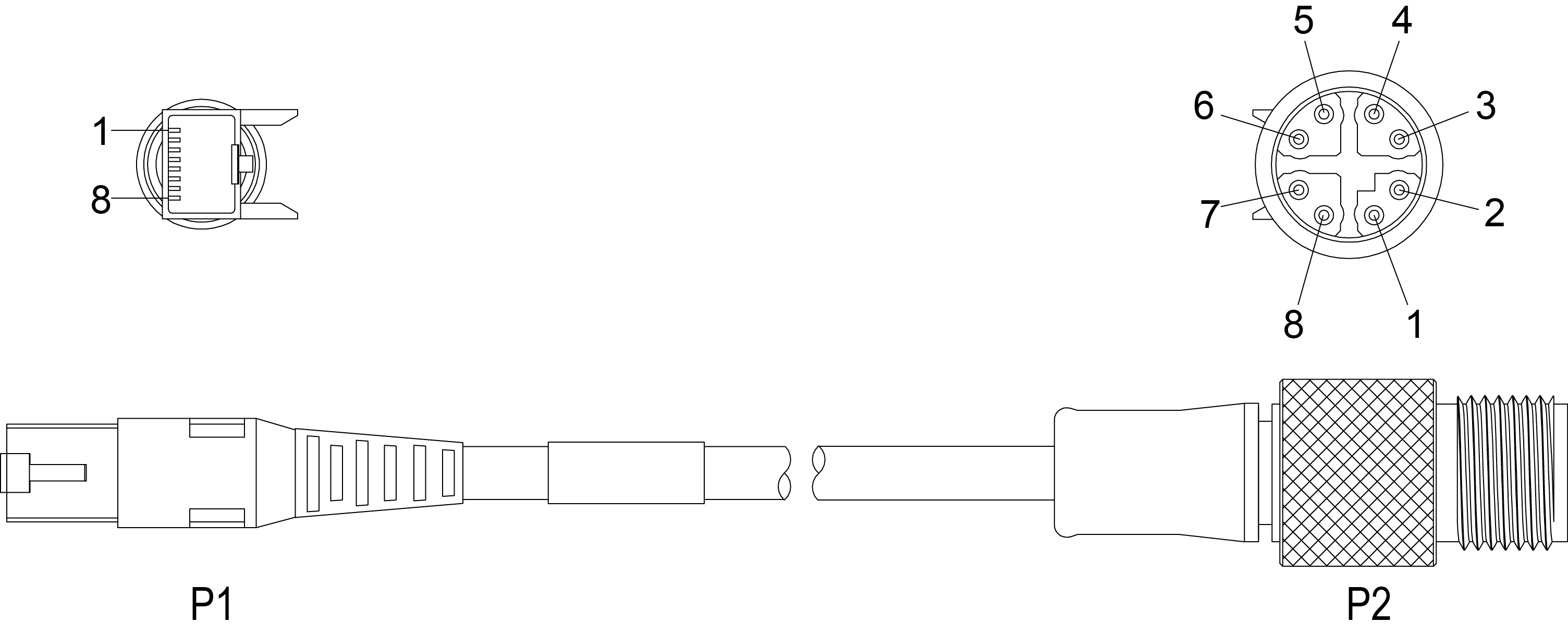
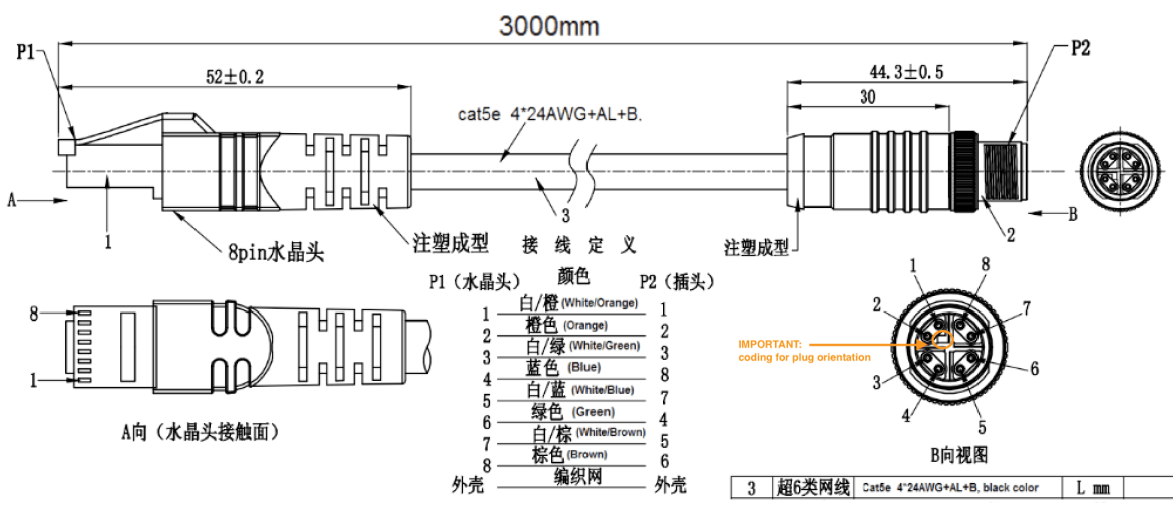
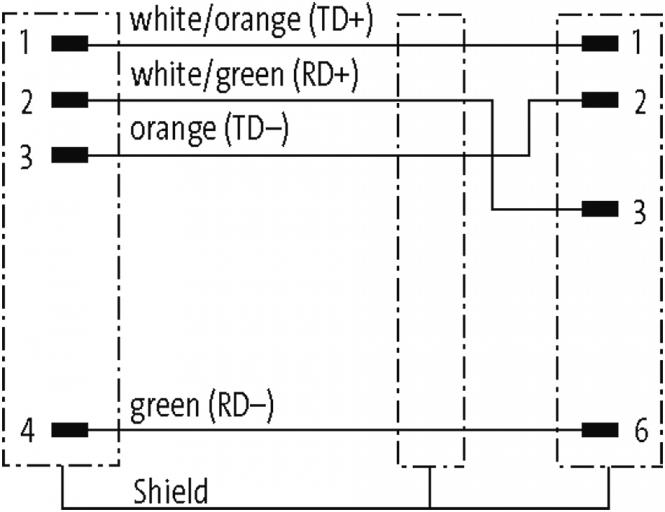
Wiring Diagram - M12 PUR/TPE Cordset Shielded, Double Ended From Pin 8 Poles To Pin 1 White/Orange 1 2 Orange 2 3 White/Green 3 4 Green 4 5 White/Brown 5 6 Brown 6 7 White/Blue 7 8 Blue 8 Shielded Metal nut Shielded M12 X-CODE CORDSET - WIRING SCHEMA Wiring Diagram - M12 PVC Cordset Shielded, Double Ended

M12 4 Pin Wiring Diagram M14 Front Panel Mount 8 Pin Wire Connector
You may identify these coding types of m12 series by below contact layout diagrams: 1. M12 A-coding Connector 3pins 4pins 5pins 8pins 12pins 17pins male pin layout diagram (front view) Application: m12 A-coding male connector is used for actuator-sensor plug connections for DeviceNet, IO link and Profibus. 2.

M12 Connector Wiring Diagram Boost Wiring
The new M12 D-coded cordsets, which are UL certified and have an IP67 rating for dust-tight and waterproof applications ensure eficient, high-quality and reliable connectivity and high integrity signal transmission.
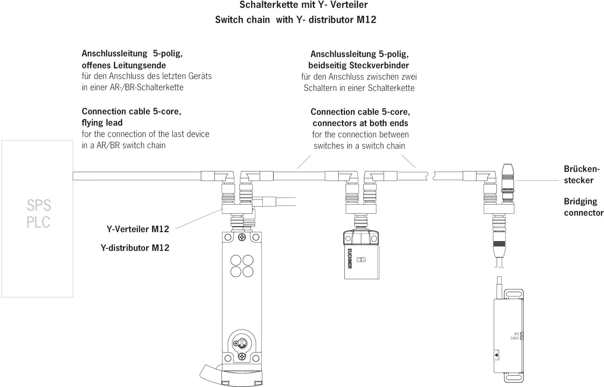
ACSPSJ097645 Bridging plug M12 EUCHNER More than safety.
M12 Ethernet wiring diagrams consist of diagrams that describe the wired connections between two devices, such as a computer, router, and network switch. The diagrams also show the physical position of each device in the network, as well as the type and speed of connection being used.
Wiring Manvier M12 DIYnot Forums
Wiring Diagrams Diagram 3 M12 connector 4-Wire NPN Output 4-Wire PNP Output Diagram 1 Diagram 2 Emitter www.automationdirect.com otoelectric Sensors tSEN-51 1-800-633-0405 For the latest prices, please check AutomationDirect.com. M12 Metal Photoelectric Sensors Specifications Sensor type Diffuse reflective (LTR) Retroreflective

M12 Wiring Diagram Cofab
The M12 connector is a circular keyed connector with a 12-mm locking thread. They provide a rugged, flexible option for connecting a wide variety of equipment.
