Center Tapped Full Wave Rectifier Full wave center tapped rectifier How to make Bridge

Center Tapped Full Wave Rectifier Full wave center tapped rectifier How to make Bridge
We can define bridge rectifiers as a type of full-wave rectifier that uses four or more diodes in a bridge circuit configuration to efficiently convert alternating (AC) current to a direct (DC) current. In the next few sections, let us learn more about its construction, working, and more. Table of Contents: Construction Working
Difference Between Center Tap Full Wave Rectifier And Bridge Rectifier CrazyEngineers
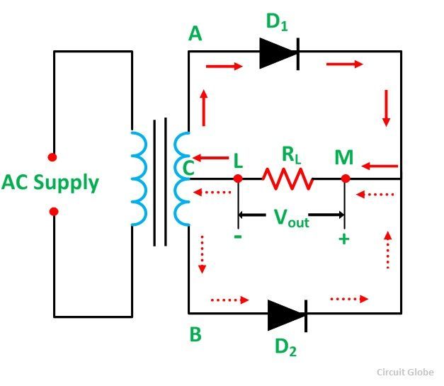
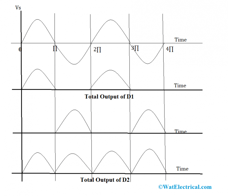
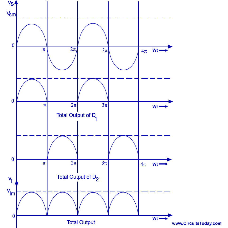
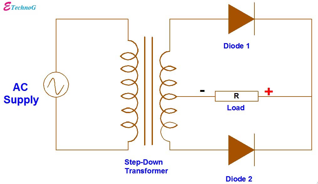
Working of Centre-Tap Full Wave Rectifier. As shown in the figure, an ac input is applied to the primary coils of the transformer. This input makes the secondary ends P1 and P2 become positive and negative alternately. For the positive half of the ac signal, the secondary point D1 is positive, GND point will have zero volt and P2 will be negative.

FULL WAVE RECTIFIER CenterTapped Bridge FullWave Rectification circuit
Power converters with higher efficiency in a wide load range are important for reducing the overall energy consumption of renewable energy generation systems. A center-tapped LC series resonant dual-active bridge (LC-DAB) converter for DC-DC conversion is proposed in this paper. The proposed converter utilizes a center-tapped bridge to block reverse current and eliminate back flow power to.

centre tapped rectifier YouTube
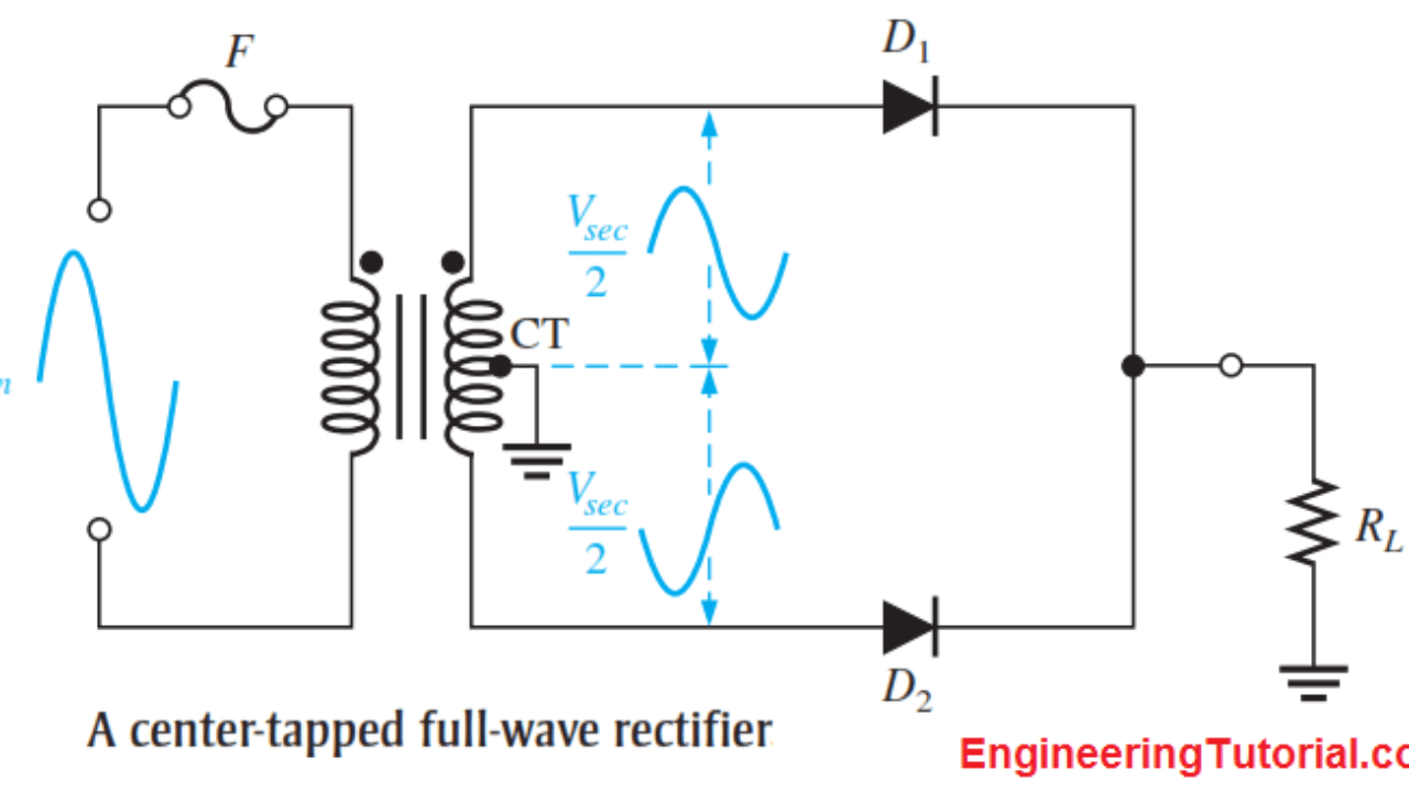
When an additional wire is connected across the exact middle of the secondary winding of a transformer, it is known as a center tapped transformer. The wire is adjusted in such a way that it falls in the exact middle point of the secondary winding. So the wire is exactly at zero volts of the AC signal. This wire is known as the center tap.
Center Tapped Full Wave Rectifier Circuit Diagram Circuit Diagram
Center Tapped Rectifier vs Bridge Rectifier Differences _Comparison of Center Tapped and Bridge Rect Simplified EEE Studies 13.5K subscribers 6.1K views 2 years ago POWER ELECTRONICS
Center Tapped Full Wave Rectifier its Operation and Wave Diagram Circuit Globe
2 I have a center-tapped transformer which outputs 12V-0V-12V. I was wondering what is the differences between using one full bridge rectifier and two to generate a positive and a negative DC rail. Consider this schematic: It uses one full bridge rectifier and uses the center tap directly as GND.

Full wave Rectifier (Center Tap & Bridge) explanation YouTube
The full-wave rectifier can be constructed in 2 ways. The first method makes use of a centre tapped transformer and 2 diodes. This arrangement is known as Center Tapped Full-Wave Rectifier. The second method uses a normal transformer with 4 diodes arranged as a bridge. This arrangement is known as a Bridge Rectifier.

CenterTapped FullWave Rectifier Operation … CircuitBread
One is center tapped full wave rectifier consisting of two diodes and one center tapped secondary winding transformer and the second is a Bridge Rectifier consisting of four diodes namely D1, D2, D3, D4 connected. Types of Rectifiers Working of Full Wave Bridge Rectifier
Center Tapped Full Wave Rectifier Operation Inst Tools
One of the differences between center-tapped and bridge rectifier is the numbers of diodes used to rectify both positive and negative half-cycles of the AC input. A bridge rectifier uses 4 diodes while a center-tapped rectifier uses only 2 diodes. Triad Magnetics VPS24-5400
CenterTapped Full Wave Rectifier Definition, Principle & Benefits
I'm designing a high-voltage power supply for a plasma experiment. I have a center-tapped ignition transformer (50:1) that I'm using to step up the voltage from 120VAC to 6kVAC and then using a full wave bridge rectifier to get +/- 6kVDC. The problem is, the design of the experiment requires me to have 0 and -12kVDC outputs, not +/- 6kVDC.
Centre Tap Full Wave Rectifier Circuit operation,Working,Diagram,Waveform
This bridge rectifier calculator can assist you in understanding how a bridge rectifier circuit works and how to use one. Bridge rectifiers convert the AC (alternating current) supply voltage to a DC (direct current) supply voltage using four diodes that are ingeniously positioned.

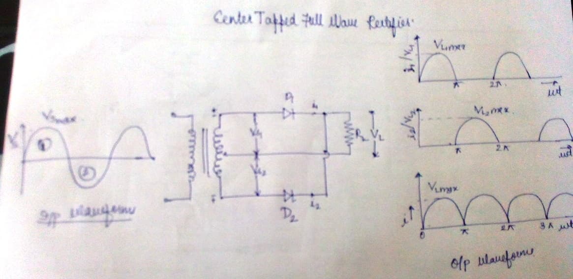
Explain with circuit diagram and waveform working of center tap full wave rectifier.
RECTIFIER - Half and Full Wave, Center tap, Bridge. Rectifier is a device which converts the alternating current (AC) into direct current (DC) and contain one or more diodes. Diode has zero resistance in one direction and infinity resistance in the other direction, so it act like short circuit in one direction and open circuit in other direction.

Rectifier Circuit Diagram Half Wave, Full Wave, Bridge ETechnoG
The only advantage of bridge rectifier over center tapped full wave rectifier is the reduction in cost. In bridge rectifier, instead of using the center-tapped transformer, four diodes are used. Now we get an idea about the three types of rectifiers. The half wave rectifier and the center tapped full wave rectifier (full wave rectifier) are.

Centre tapped transformers and bridge rectifiers for dual PSU pink fish media
Centre tapped Rectifier consists of two diodes which are connected to the centre tapped secondary winding of the transformer as well as with the load resistor. Bridge rectifier comprises of 4 diodes which are connected in the form of Wheat stone bridge and thus provide full wave rectification.

CenterTapped FullWave Rectifier Operation … CircuitBread
A center tapped full wave rectifier is a type of rectifier which uses a center tapped transformer and two diodes to convert the complete AC signal into DC signal. Load resistor, an AC source, two diodes and a center tapped transformer are the main components of a center tapped full wave rectifier.
Bipolar Output Full Wave Bridge Rectifier with Center Tapped Transformer. ETechnoG
Centre-tapped and bridge rectifiers are both types of full-wave rectifiers, i.e., both of these convert full cycle of AC into DC. But, their circuit configuration and working is different. Some important differences between centre-tapped rectifier and bridge rectifier are discussed in the above table.
