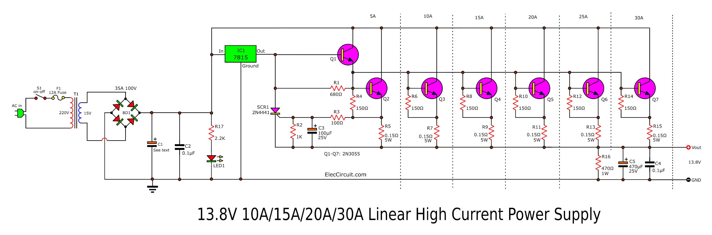
High current adjustable power supply circuit, 030V 20A
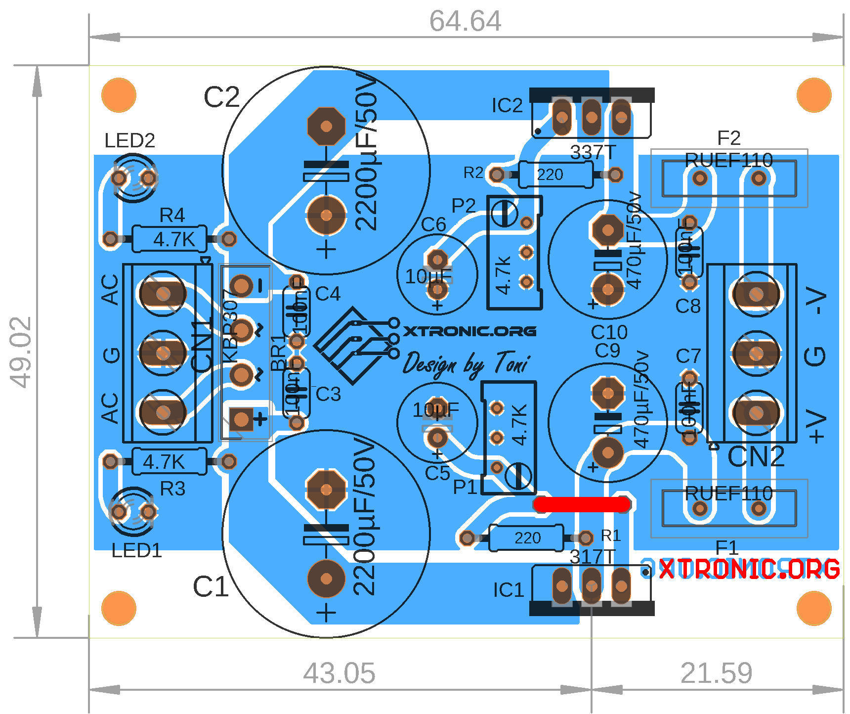
Adjustable Symmetrical Power Supply With LM317 and LM337 Xtronic
There are two basic categories of power factor improvement circuits namely active and passive. A typical active P.F.C. circuit supplies a regulated DC bus at higher voltage then the maximum peak voltage of the AC supply and uses a simple boost topology as shown in Fig. 1. The boost topology of Fig. 1 may be operated at
LM317based highcurrent adjustable power supply — Curious Scientist
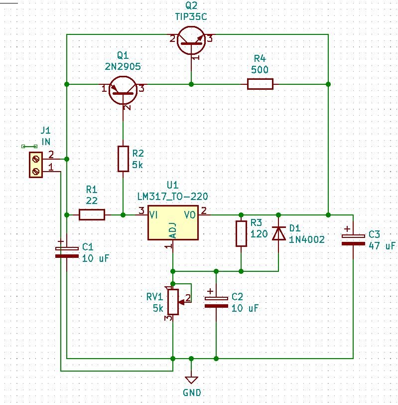
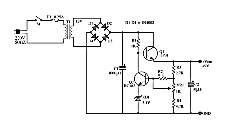
In this circuit, we are going to make a 24 Volt LM317 5A Variable Or Adjustable Power Supply. LM317 is a fully adjustable positive voltage regulator IC. It gives an output of 1.25V to 37V and is capable of supplying a 1.5A output current. This IC is convenient and uses only two external resistors to set the value of the desired output voltage.
Adjustable 0100V 50 Amp SMPS Circuit Circuit Diagram Centre
Circuit Diagram of Adjustable DC Power Supply Circuit using LM317 Variable Voltage Regulator. Working Principle. According to the LM317 datasheet, this voltage regulator Output voltage can be set to range from 1.25V to 37V, and the max output current is 1.5A. Here, we have used 220V to 24V 1.5A step-down transformer which converts 220v high.
040V adjustable voltage regulator at 1A
Step 1: The Parts List We need these following parts to build the power supply. I bought some from online and some from the local store. Parts List: LTC3780 DC Adjustable Converter Digital Voltmeter Ammeter Display
Adjustable Power Supply Circuit Diagrams
The LM317T is an adjustable 3-terminal positive voltage regulator capable of supplying different DC voltage outputs other than the fixed voltage power supply of +5 or +12 volts, or as a variable output voltage from a few volts up to some maximum value all with currents of about 1.5 amperes.
Adjustable Dc Power Supply Circuit Diagram
In this project, an adjustable power supply circuit is designed which inputs AC mains and provides 0 to 30V 2A DC Voltage as output. The power supply designed in this project is an adjustable linear regulated type so the output voltage of the circuit is constant and is varied mechanically with the help of a variable resistor.

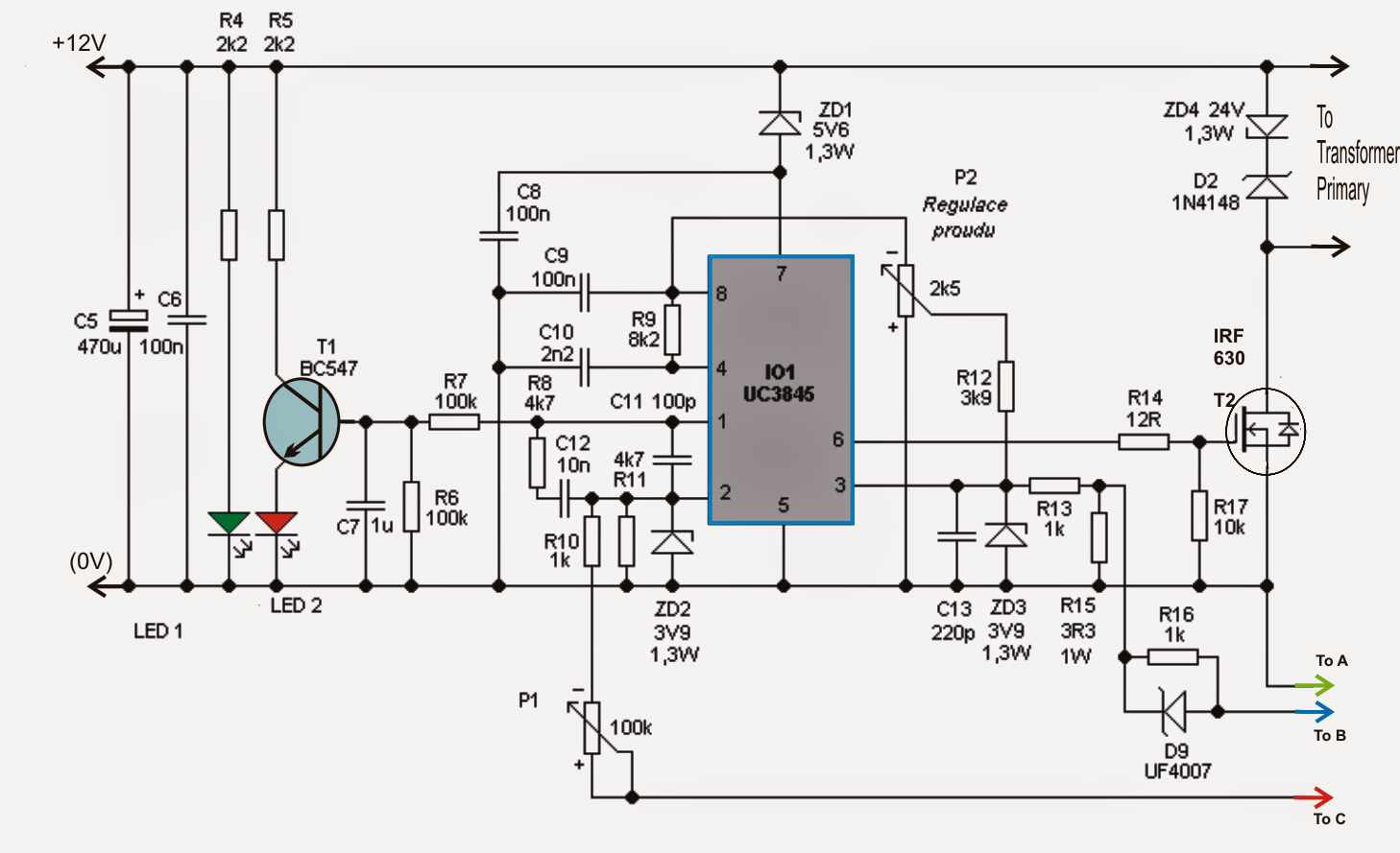
Adjustable Current Switch Mode Power Supply (SMPS) Circuit
Buy DC Power Supply Variable, Bench Power Supply with Encoder knob, Adjustable Switching Power Supply with OCP Switch, Variable Power Supply with Output Enable/Disable Button (0-60V 0-20A): Power Supplies - Amazon.com FREE DELIVERY possible on eligible purchases
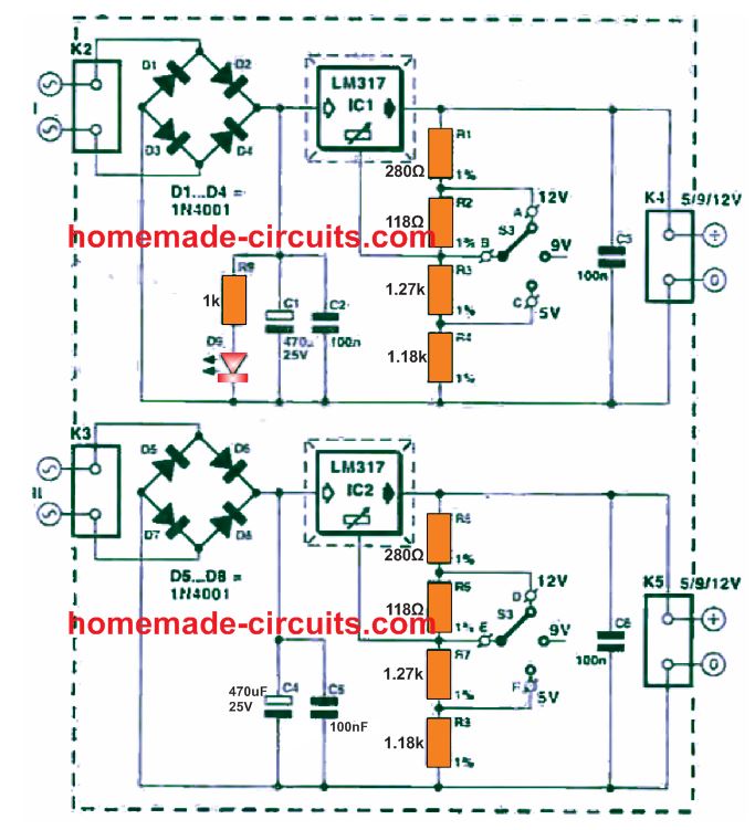
Adjustable 3V, 5V, 6V, 9V,12V,15V Dual Power Supply Circuit Homemade Circuit Projects
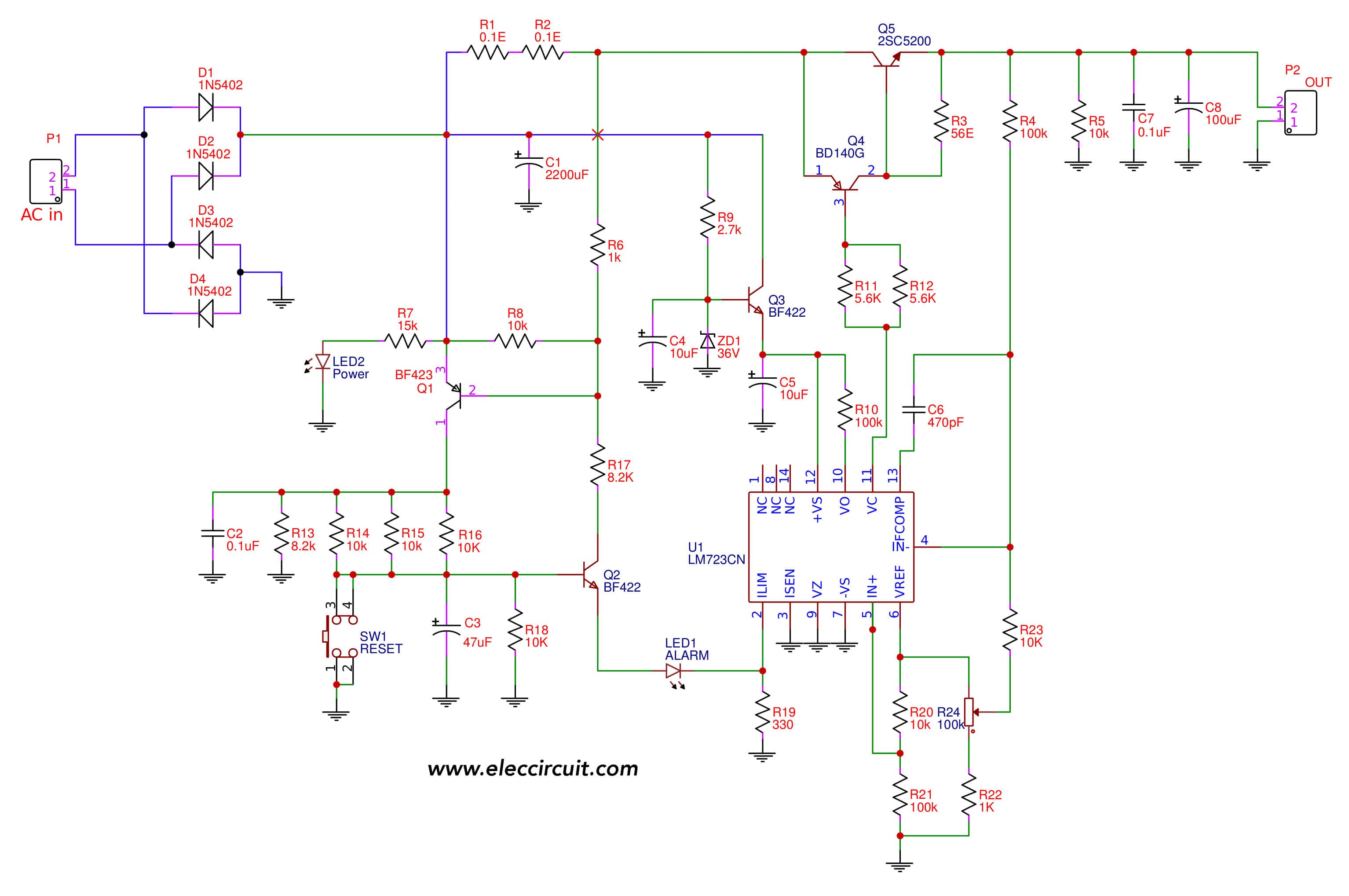
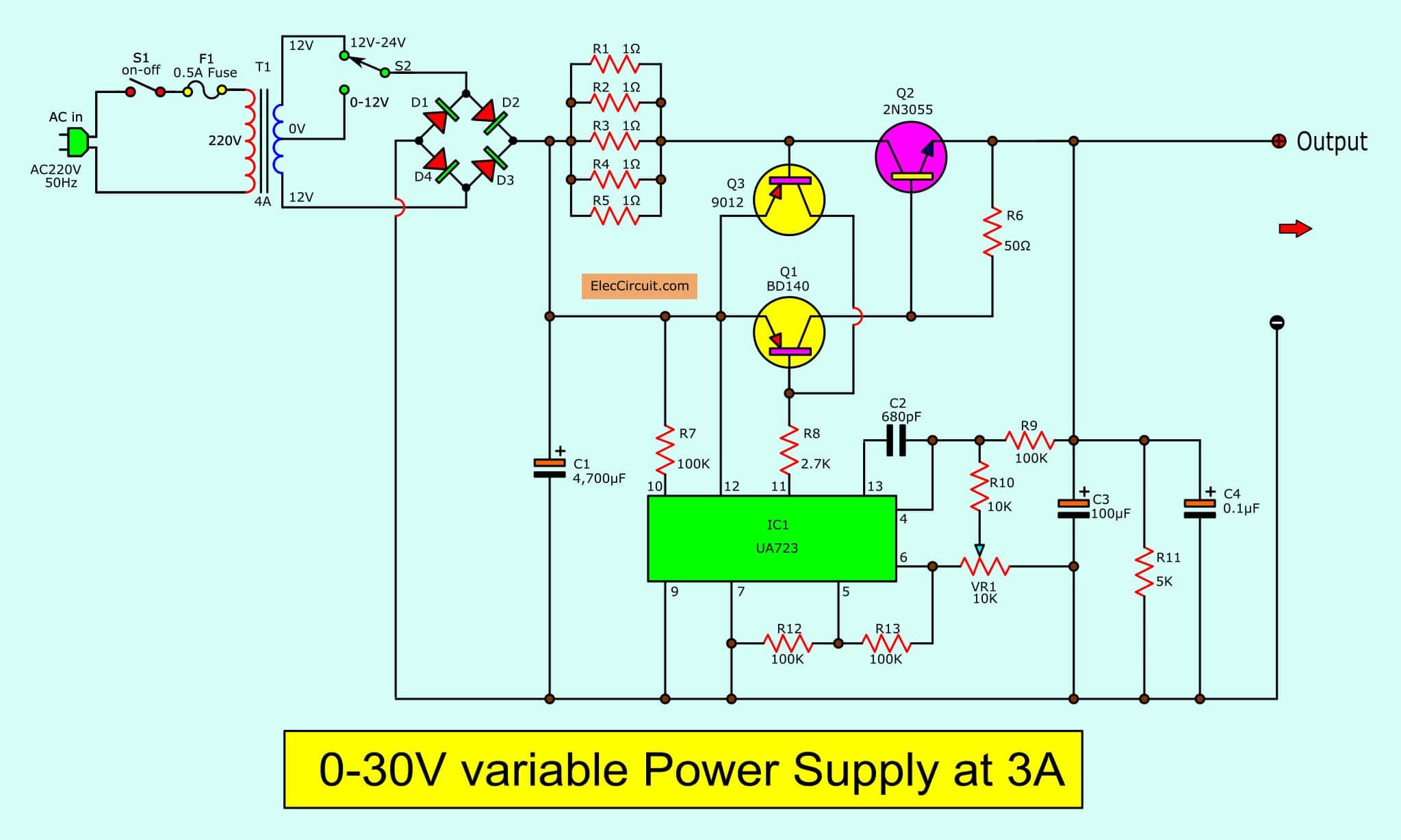
With conveniently adjustable output voltage from 0V to 30V, at 3A current, and overload protection. Also, it is a high-efficiency regulator by using a UA723 IC-regulator, and a TIP3055 power transistor. So, it is a great pick for a small laboratory DC Power Supply usage at an inexpensive cost.

030v 010A variable power supply Adjustable voltage and current YouTube
Step 1: Components Required: 1. LM317 IC with heat sink 1no 2. 10 uF Capacitor 1no 3. 1000 uF Capacitors 2no 4. 0.1uF Capacitors 2no 5. 1k resistor 1no 6. 240-ohm resistor 1no 7. 5k potentiometer 1no 8. 1N4007 Diodes 6no 9. 5-mm LED 1no 10. Step Down Transformer 220/110V to 15v 11. Digital Voltmeter 0-100V Three Wire (Optional) 12. Connectors
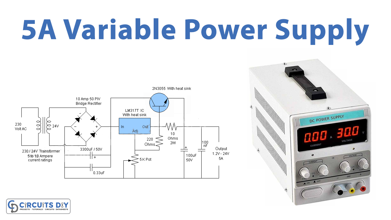
5A Variable OR Adjustable Power Supply LM317
Top 8 power supply circuits Other Linear Power Supply Circuit Diagram Fixed Volts regulator: Adjustable Power Supply Circuit Switching Mode Power Supply circuits Switching Mode regulator DC to DC converter Related Posts 3 Power Source for Electronic Devices Let's look at the three most used types of Power Supplies. Types 1# Battery
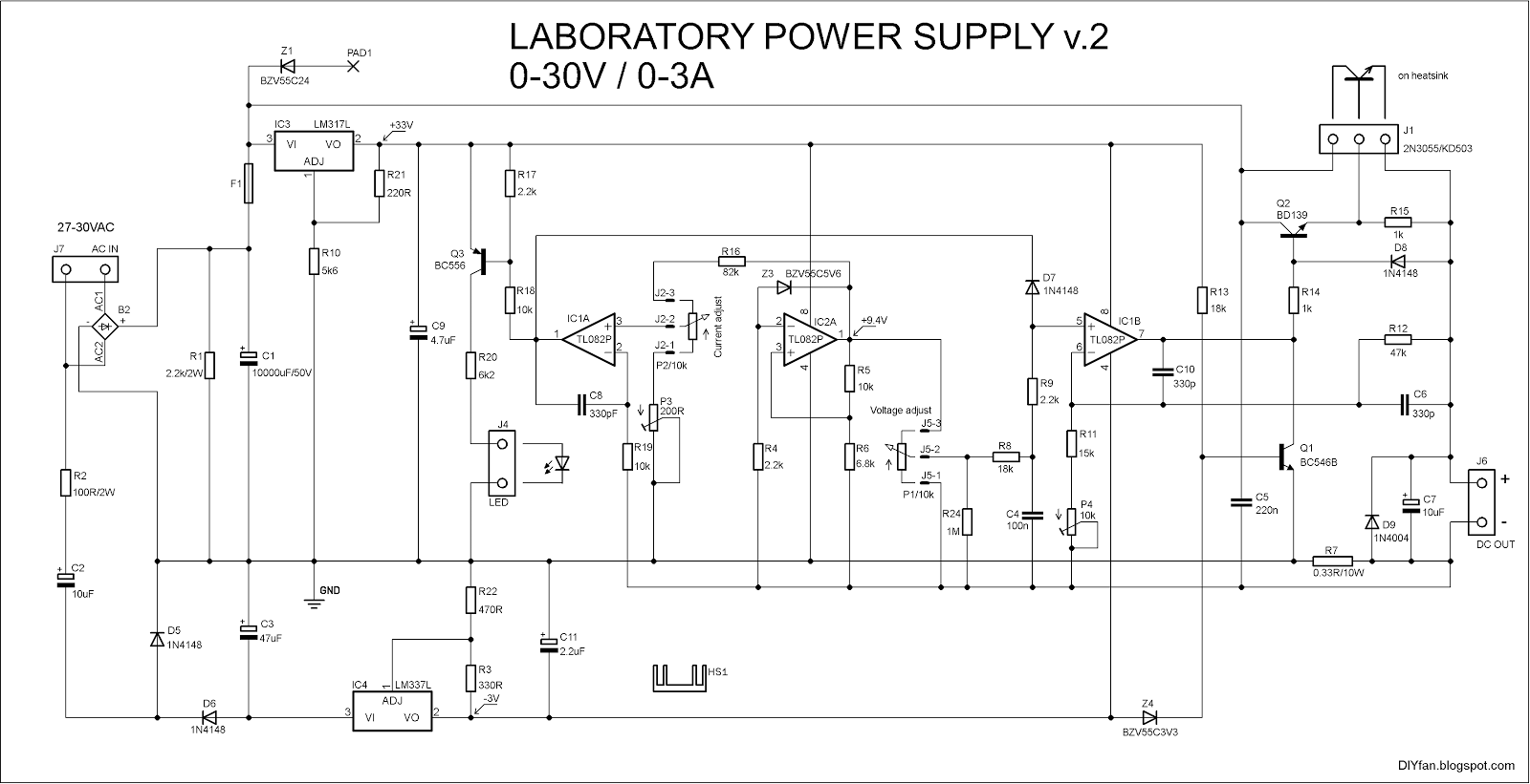
DIYfan Adjustable Lab Power Supply take two )
Step 1: Mount and Solder the Components As Presented in the Schematic Diagram To start designing this circuit, you will need a heat sink to attach LM317, BD139 and TP3055 transistors. Then, mount these components on a PCB board and cut the extra legs of the components soldered with a cutting plier.
030V Variable Power Supply circuit Diagram at 3A
The aim of the dual adjustable power supply circuit is to provide power for other projects that require a dual (+/-) adjustable power supply. This is the circuit diagram of a dual adjustable power supply using IC's LM 317 & LM 337. LM317 is able to deliver a maximum of 1.5 A at a range of 1.2 V to +30V. LM317 is a positive voltage regulator.

Variable / Adjustable DC Power Supply 1.2V 25V using LM338K Schematic Design
An adjustable power supply is a device that provides a variable output voltage and current to power electronic circuits and devices. It is an essential tool for electronics enthusiasts and professionals who need to test and troubleshoot different types of electrical and electronic systems.
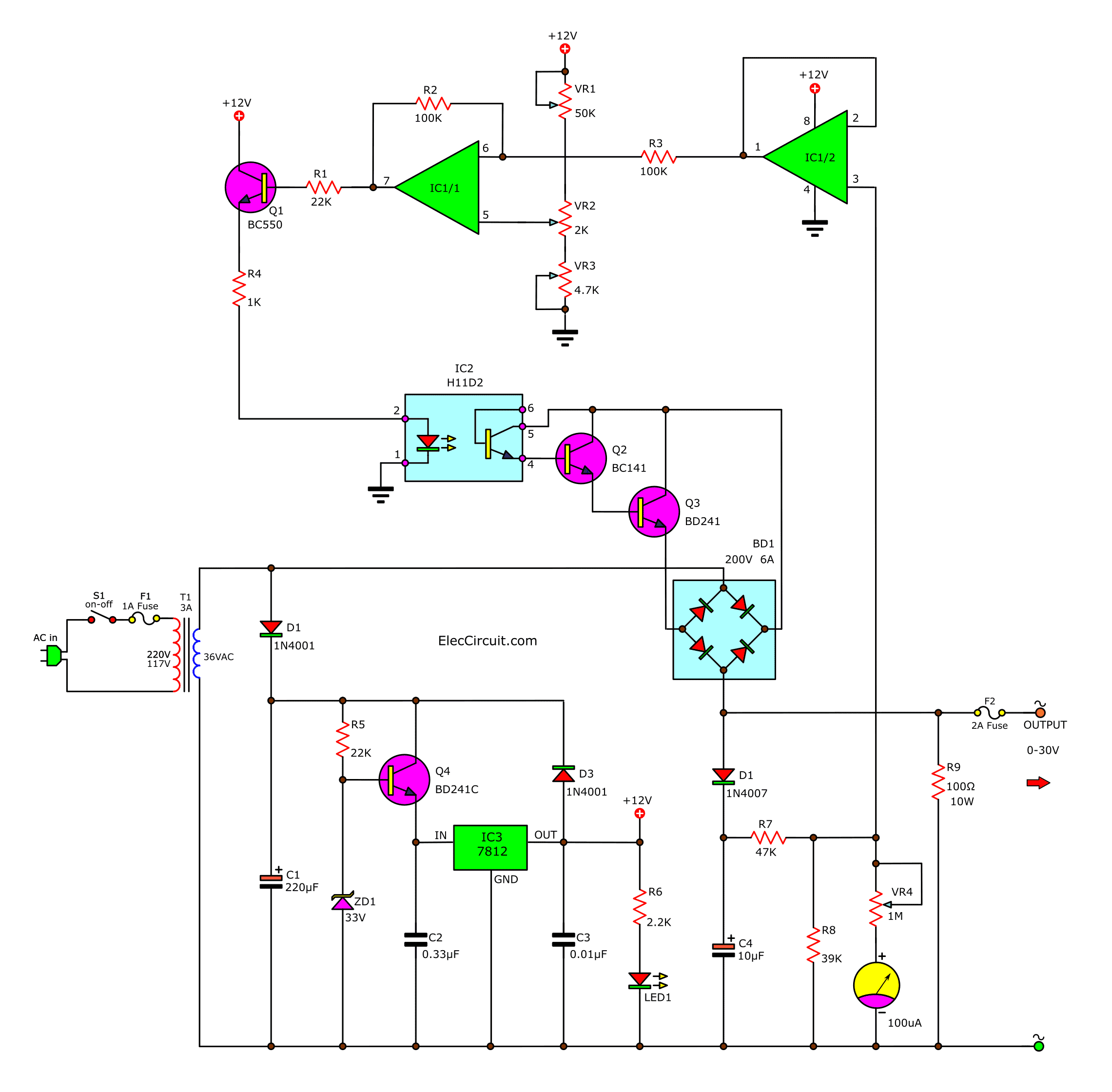
AC variable power supply, 030V 3A
Here is the LM338 Adjustable DC power supply circuit, 1.2V to 30V. It can provide a current maximum to 5A and 10A. If you have used LM317 or LM350. They are similar, so easy to use with a few components. But LM338 has higher a current than LM317. You can look at a datasheet below more spec. Table of Contents hide LM338 Datasheet and Pinout
Adjustable Power Supply Circuit Diagrams
A simple and locally adjustable power supply uses a potentiometer or other voltage regulating devices to adjust the voltage or current at the output. This post explains the working of a variable DC power supply circuit that has an adjustable voltage range of 1.2V to 24V and current up to 5A. It has many features like short-circuit protection.
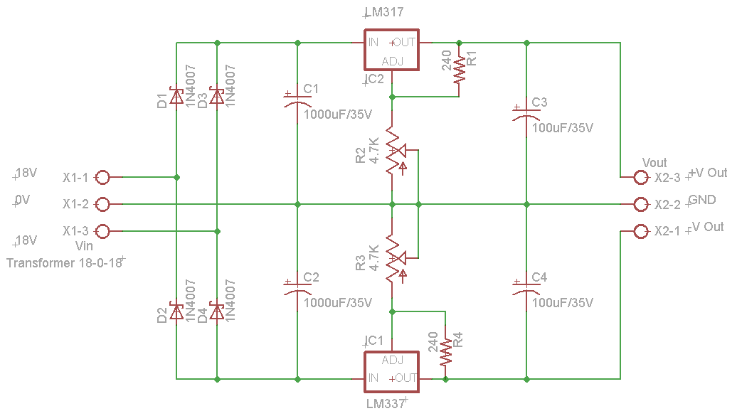
Dual Adjustable DC Power Supply
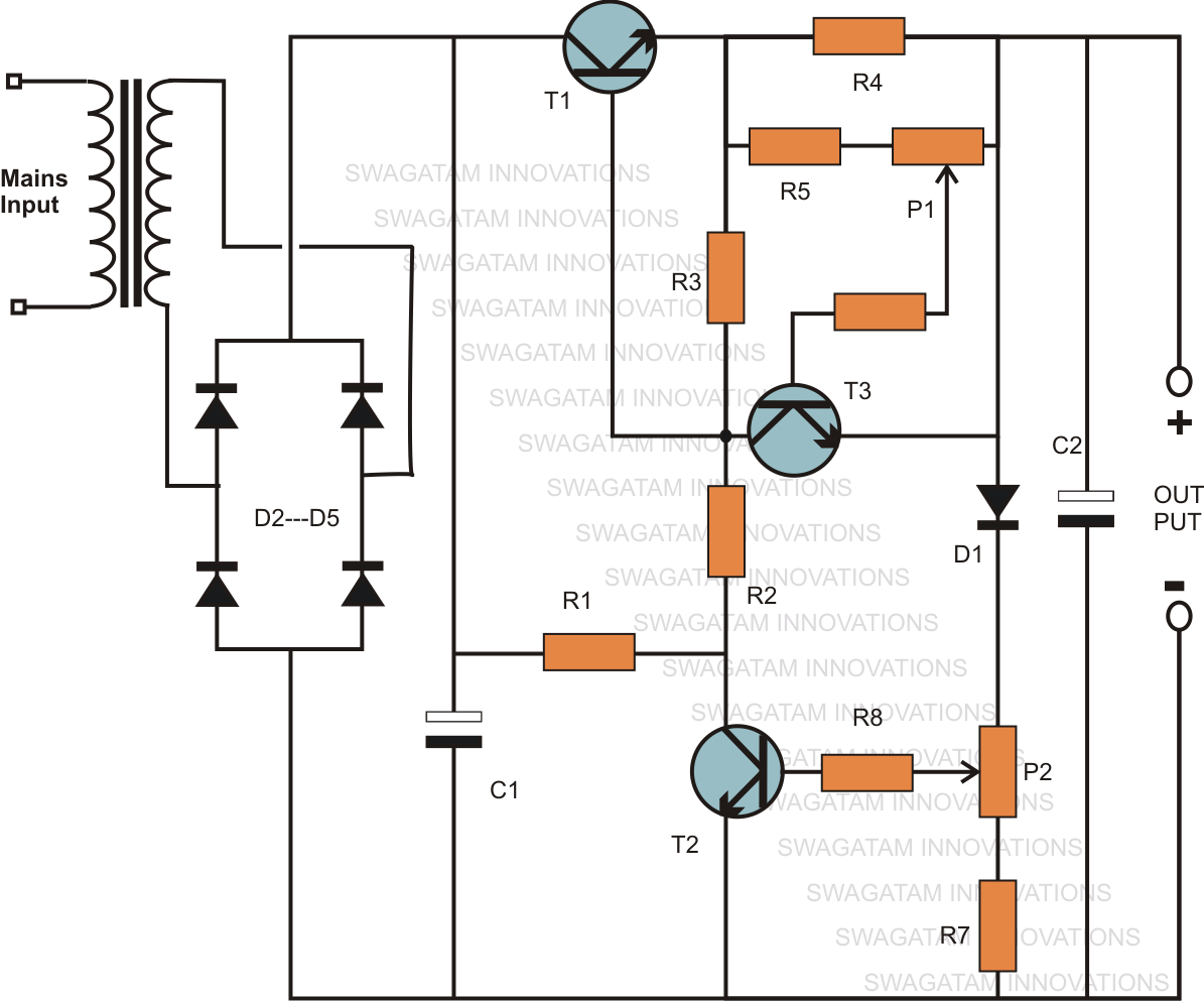
Whether it's an electronic noob or an expert professional, an adjustable power supply unit is required by everybody in the field. It is the basic source of power that may be required for various electronic procedures, right from powering intricate electronic circuits to the robust electromechanical devices like motors, relays etc.
